
Fluke 1750 Operators Manual
Page 1
1750 Power Recorder Operators Manual October 2006 Rev.3, 11/10 © 2006-2010 Fluke Corporation. All rights reserved. Specifications are trademarks of their respective companies. All product names are subject to change without notice.
1750 Power Recorder Operators Manual October 2006 Rev.3, 11/10 © 2006-2010 Fluke Corporation. All rights reserved. Specifications are trademarks of their respective companies. All product names are subject to change without notice.
Fluke 1750 Operators Manual
Page 4
... Transient Voltage (Impulse 51 Dip (Sag) and Swell Measurements 51 Power and PF Measurement 51 External Interface Specifications 52 Environmental and Safety Specifications 52 ii 1750 Operators Manual Setting Up the Recorder 38 Setting the Clock 40 Probe Detect 40 Setting the IP Address 41 Adding a Measurement Description 41 Configure Nominal Power Values...
... Transient Voltage (Impulse 51 Dip (Sag) and Swell Measurements 51 Power and PF Measurement 51 External Interface Specifications 52 Environmental and Safety Specifications 52 ii 1750 Operators Manual Setting Up the Recorder 38 Setting the Clock 40 Probe Detect 40 Setting the IP Address 41 Adding a Measurement Description 41 Configure Nominal Power Values...
Fluke 1750 Operators Manual
Page 10
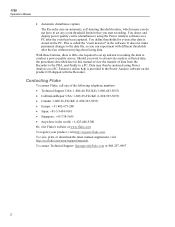
...the procedures described later in this manual review the transfer of the following telephone numbers: • Technical Support USA: 1-800-44-FLUKE (1-800-443-5853) • Calibration/Repair USA: 1-888-99-FLUKE (1-888-993-5853) • Canada: 1-800-36-FLUKE (1-800-363-5853) •... Analyze software on a PC. To register your product, visit http://register.fluke.com. To view, print, or download the latest manual supplement, visit http://us.fluke.com/usen/support/manuals. 1750 Operators Manual • Automatic disturbance capture The Recorder uses an automatic, self-learning threshold...
...the procedures described later in this manual review the transfer of the following telephone numbers: • Technical Support USA: 1-800-44-FLUKE (1-800-443-5853) • Calibration/Repair USA: 1-888-99-FLUKE (1-888-993-5853) • Canada: 1-800-36-FLUKE (1-800-363-5853) •... Analyze software on a PC. To register your product, visit http://register.fluke.com. To view, print, or download the latest manual supplement, visit http://us.fluke.com/usen/support/manuals. 1750 Operators Manual • Automatic disturbance capture The Recorder uses an automatic, self-learning threshold...
Fluke 1750 Operators Manual
Page 12
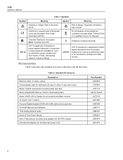
Contact Fluke or a qualified recycler for details 2277216 2441360 2386780 2386771 2386767 2436261 2583479 2441372 4 Accessories Table 2 describes the standard accessories that ship with USB cable and accessories CD-ROM Manuals and Software 1750 Getting Started Guide Sheet of Front Panel Decals...plug adapters for the PDA charger International adapters for the Recorder power cord Part Number 2402854 2157607 2157713 Call for disposal. 1750 Operators Manual Table 1. Canadian Standards Association. [Note: Canadian and US.] CAT III equipment is designed to protect against transients in ...
Contact Fluke or a qualified recycler for details 2277216 2441360 2386780 2386771 2386767 2436261 2583479 2441372 4 Accessories Table 2 describes the standard accessories that ship with USB cable and accessories CD-ROM Manuals and Software 1750 Getting Started Guide Sheet of Front Panel Decals...plug adapters for the PDA charger International adapters for the Recorder power cord Part Number 2402854 2157607 2157713 Call for disposal. 1750 Operators Manual Table 1. Canadian Standards Association. [Note: Canadian and US.] CAT III equipment is designed to protect against transients in ...

Fluke 1750 Operators Manual
Page 14
..., insert in the PDA and transfer data to different ground potentials creates a ground loop that a safety ground connection does exist through the line power cord. 1750 Operators Manual Table 3. TCP/IP via the "synchronize data" feature of probe range, use the supplemental ground terminal only when no protective earth ground connection exists through...
..., insert in the PDA and transfer data to different ground potentials creates a ground loop that a safety ground connection does exist through the line power cord. 1750 Operators Manual Table 3. TCP/IP via the "synchronize data" feature of probe range, use the supplemental ground terminal only when no protective earth ground connection exists through...

Fluke 1750 Operators Manual
Page 16
See Caution Above Potential Ground Loop Optional Protective Chassis Ground (See detail below) Different Power System Line Power Cord Power Network Being Measured ØB OK Correct, No Ground Loop ØA Incorrect, Creates Ground Loop GND Figure 3. Connecting the Supplemental Ground Terminal ØC N azd11f.eps 8 1750 Operators Manual WCaution Connecting the supplemental ground terminal and the line cord safety ground to different ground potentials creates a ground loop that can damage the Recorder.
See Caution Above Potential Ground Loop Optional Protective Chassis Ground (See detail below) Different Power System Line Power Cord Power Network Being Measured ØB OK Correct, No Ground Loop ØA Incorrect, Creates Ground Loop GND Figure 3. Connecting the Supplemental Ground Terminal ØC N azd11f.eps 8 1750 Operators Manual WCaution Connecting the supplemental ground terminal and the line cord safety ground to different ground potentials creates a ground loop that can damage the Recorder.

Fluke 1750 Operators Manual
Page 18
When Power View operates for the first time on your CD-ROM drive. 10 Administrator privileges are required to choose between the phase identifiers A, ...; Microsoft Excel 2000 or higher WCaution Do not remove the CD until after a hard reset, it directly opens the language setup window. 1750 Operators Manual Language Selection Power View features a localized user interface for Power Analyze • Windows 2000, Windows XP, Windows Vista 32/64bit, Windows ...• 1024 x 768 or higher resolution video. • Keyboard and mouse. This window is also accessed by Menu>1750 Setup>Language.
When Power View operates for the first time on your CD-ROM drive. 10 Administrator privileges are required to choose between the phase identifiers A, ...; Microsoft Excel 2000 or higher WCaution Do not remove the CD until after a hard reset, it directly opens the language setup window. 1750 Operators Manual Language Selection Power View features a localized user interface for Power Analyze • Windows 2000, Windows XP, Windows Vista 32/64bit, Windows ...• 1024 x 768 or higher resolution video. • Keyboard and mouse. This window is also accessed by Menu>1750 Setup>Language.
Fluke 1750 Operators Manual
Page 20
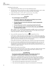
... with the PDA stylus. After a minute, or two, all LEDs should flash ON, then OFF, and then each should turn ON and OFF in this manual. Upon selection, the Home screen for recorder when first connecting. If more secure than one Recorder is established for the Recorder, you should attach the... for a specific Recorder using the appropriate supplied adapter. • Connect the power cord to a properly grounded wall outlet. • Be sure to the Recorder. 12 1750 Operators Manual Installing the Recorder 1. If a Recorder is within 2 m (6 ft) of the monitoring location. 2.
... with the PDA stylus. After a minute, or two, all LEDs should flash ON, then OFF, and then each should turn ON and OFF in this manual. Upon selection, the Home screen for recorder when first connecting. If more secure than one Recorder is established for the Recorder, you should attach the... for a specific Recorder using the appropriate supplied adapter. • Connect the power cord to a properly grounded wall outlet. • Be sure to the Recorder. 12 1750 Operators Manual Installing the Recorder 1. If a Recorder is within 2 m (6 ft) of the monitoring location. 2.

Fluke 1750 Operators Manual
Page 22
... does so automatically, overwriting the oldest data (circular memory). Downloading to a PC running Fluke Power Analyze Software (included) using the Ethernet cable is recommended and the fastest way to record, it using the PDA or an attached PC. 1750 Operators Manual descriptions such as an aid in Power View or Power Analyze software. This...
... does so automatically, overwriting the oldest data (circular memory). Downloading to a PC running Fluke Power Analyze Software (included) using the Ethernet cable is recommended and the fastest way to record, it using the PDA or an attached PC. 1750 Operators Manual descriptions such as an aid in Power View or Power Analyze software. This...

Fluke 1750 Operators Manual
Page 24
1750 Operators Manual GND A/L1 GND B/L2 POWER 1750 POWER RECORDER VOLTAGE A B C N 100-240 V 47- 63 Hz ON CURRENT SD ETHERNET LINK BUSY Figure 5. One-Phase IT No Neutral azd14f.eps Example: Used in Norway and in some hospitals. This would be the connection at a branch circuit. 16
1750 Operators Manual GND A/L1 GND B/L2 POWER 1750 POWER RECORDER VOLTAGE A B C N 100-240 V 47- 63 Hz ON CURRENT SD ETHERNET LINK BUSY Figure 5. One-Phase IT No Neutral azd14f.eps Example: Used in Norway and in some hospitals. This would be the connection at a branch circuit. 16

Fluke 1750 Operators Manual
Page 26
Typical commercial building power. 18 Three-Phase Wye azd04f.eps Example: Also called "Star" or four-wire connection. 1750 Operators Manual Source ØA/L1 GND ØC/L3 ØB/L2 A/L1 GND N B/L2 C/L3 POWER 1750 POWER RECORDER VOLTAGE A B C N 100-240 V 47-63Hz ON CURRENT SD ETHERNET LINK BUSY Figure 7.
Typical commercial building power. 18 Three-Phase Wye azd04f.eps Example: Also called "Star" or four-wire connection. 1750 Operators Manual Source ØA/L1 GND ØC/L3 ØB/L2 A/L1 GND N B/L2 C/L3 POWER 1750 POWER RECORDER VOLTAGE A B C N 100-240 V 47-63Hz ON CURRENT SD ETHERNET LINK BUSY Figure 7.

Fluke 1750 Operators Manual
Page 28
Three-Phase IT azd12f.eps Example: Industrial power in countries that use the IT (Isolated Terra) system, such as Norway. 20 1750 Operators Manual ØA /L1 ØC/L3 GND ØB/L2 A/L1 GND B/L2 C/L3 POWER 1750 POWER RECORDER VOLTAGE A B C N 100-240 V 47-63 Hz ON CURRENT SD ETHERNET LINK BUSY Figure 9.
Three-Phase IT azd12f.eps Example: Industrial power in countries that use the IT (Isolated Terra) system, such as Norway. 20 1750 Operators Manual ØA /L1 ØC/L3 GND ØB/L2 A/L1 GND B/L2 C/L3 POWER 1750 POWER RECORDER VOLTAGE A B C N 100-240 V 47-63 Hz ON CURRENT SD ETHERNET LINK BUSY Figure 9.

Fluke 1750 Operators Manual
Page 30
Three-Phase Open Leg Example: A variant of power transformer winding type. A/L1 GND B/L2 C/L3 azd18f.eps 22 1750 Operators Manual ØC/L3 ØA/L1 GND ØB/L2 POWER 1750 POWER RECORDER VOLTAGE A B C N 100-240 V 47-63Hz ON CURRENT SD ETHERNET LINK BUSY Figure 11.
Three-Phase Open Leg Example: A variant of power transformer winding type. A/L1 GND B/L2 C/L3 azd18f.eps 22 1750 Operators Manual ØC/L3 ØA/L1 GND ØB/L2 POWER 1750 POWER RECORDER VOLTAGE A B C N 100-240 V 47-63Hz ON CURRENT SD ETHERNET LINK BUSY Figure 11.

Fluke 1750 Operators Manual
Page 32
azd07f.eps 24 1750 Operators Manual ØA/L1 ØC/L3 ØB/L2 A/L1 GND N B/L2 No Connection to 1750 voltage input C/L3 P OWE R 1750 P OWER RECORDE R VOLT AG E A B C N 100-240 V 47-63Hz ON CURRENT SD ETHERNET LINK B US Y Figure 13. 2 ½-Element Wye Example: Blondel or Aron system for 4-wire (Wye) power secondaries.
azd07f.eps 24 1750 Operators Manual ØA/L1 ØC/L3 ØB/L2 A/L1 GND N B/L2 No Connection to 1750 voltage input C/L3 P OWE R 1750 P OWER RECORDE R VOLT AG E A B C N 100-240 V 47-63Hz ON CURRENT SD ETHERNET LINK B US Y Figure 13. 2 ½-Element Wye Example: Blondel or Aron system for 4-wire (Wye) power secondaries.

Fluke 1750 Operators Manual
Page 34
1750 Operators Manual Navigating in the Recorder and for erasing Recorder internal memory and erasing SD card files. 1750 Setup Brings up a list of interest or the Live menu. Once a detail view is selected, navigation to all available detail views is accomplished using the ...
1750 Operators Manual Navigating in the Recorder and for erasing Recorder internal memory and erasing SD card files. 1750 Setup Brings up a list of interest or the Live menu. Once a detail view is selected, navigation to all available detail views is accomplished using the ...

Fluke 1750 Operators Manual
Page 36
1750 Operators Manual Menu Tree The following figure provides an overview of the Power View menu structure that will be helpful in navigating through the Power View application. Erase 1750 Memory Fluke Power View 1750 Power Recorders Found Connecting 1750 Power Recorder Not Found Live Scope Meter Phasor Harmonics Trend Home Menu Tools 1750 Setup Exit 1750 Download Write to...
1750 Operators Manual Menu Tree The following figure provides an overview of the Power View menu structure that will be helpful in navigating through the Power View application. Erase 1750 Memory Fluke Power View 1750 Power Recorders Found Connecting 1750 Power Recorder Not Found Live Scope Meter Phasor Harmonics Trend Home Menu Tools 1750 Setup Exit 1750 Download Write to...

Fluke 1750 Operators Manual
Page 38
If your recorder is set, the Password screen appears instead. If password protection is not listed, but in range, press "Search New Devices" to update the list. Azd113.bmp If the selected Recorder is password protected. Azd114.bmp 30 An asterisk preceding the Recorder name means that unit is not password protected, the Home screen appears. 1750 Operators Manual If more than one Recorder is within range, the Recorder selection screen appears.
If your recorder is set, the Password screen appears instead. If password protection is not listed, but in range, press "Search New Devices" to update the list. Azd113.bmp If the selected Recorder is password protected. Azd114.bmp 30 An asterisk preceding the Recorder name means that unit is not password protected, the Home screen appears. 1750 Operators Manual If more than one Recorder is within range, the Recorder selection screen appears.

Fluke 1750 Operators Manual
Page 40
Azd107s.bmp You can also access the SD card to erase the SD card before downloading. 1750 Operators Manual Azd117.bmp If the SD storage card already contains data files, it may not have room for the new download. Power View alerts you to this condition and asks if you would like to delete files by selecting Tools>1750 SD Memory from the Data menu option. 32
Azd107s.bmp You can also access the SD card to erase the SD card before downloading. 1750 Operators Manual Azd117.bmp If the SD storage card already contains data files, it may not have room for the new download. Power View alerts you to this condition and asks if you would like to delete files by selecting Tools>1750 SD Memory from the Data menu option. 32

Fluke 1750 Operators Manual
Page 42
All of the functions (controller, PDA, and Power View) are duplicated in the 1750 Live mode. Azd119.bmp 34 1750 Operators Manual Azd109s.bmp When you sure?" Note You can also download data by connecting your PC directly to Erase All, the following popup caution "Are you choose to the Recorder with an Ethernet cable and run Power Analyze in 1750 Live mode. appears on the screen.
All of the functions (controller, PDA, and Power View) are duplicated in the 1750 Live mode. Azd119.bmp 34 1750 Operators Manual Azd109s.bmp When you sure?" Note You can also download data by connecting your PC directly to Erase All, the following popup caution "Are you choose to the Recorder with an Ethernet cable and run Power Analyze in 1750 Live mode. appears on the screen.

Fluke 1750 Operators Manual
Page 44
1750 Operators Manual Meter Screen The Meter screen shows numeric readings for additional information. This...of voltage and current on the PHASOR diagram. You can easily correct an erroneous Recorder connection by going directly to Menu\1750 Setup\Phase Swap ( ) and using the Recorder to internally invert a CT, swap a voltage or CT phase, or... screen to verify proper test lead and current probe connections. Azd123.bmp 36 See "Phase Swap" later in the manual for all selected phases. Azd122.bmp Phasor Screen The Phasor screen shows voltage (long arrows with solid arrowheads), current ...
1750 Operators Manual Meter Screen The Meter screen shows numeric readings for additional information. This...of voltage and current on the PHASOR diagram. You can easily correct an erroneous Recorder connection by going directly to Menu\1750 Setup\Phase Swap ( ) and using the Recorder to internally invert a CT, swap a voltage or CT phase, or... screen to verify proper test lead and current probe connections. Azd123.bmp 36 See "Phase Swap" later in the manual for all selected phases. Azd122.bmp Phasor Screen The Phasor screen shows voltage (long arrows with solid arrowheads), current ...
