
Fluke 1750 Three Phase Power Recorder Datasheet
Page 1
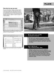
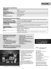
...instrument is recording, even in awkward test locations. • Threshold-free setup: Apply thresholds after data is collected with Fluke Power Analyze Software so there is no need to incorrect set-up in minutes with IEC61000-4-30 standards for correct evaluation of even ...Quickly retrieve data: With included SD memory card or via the 100BaseT high-speed Ethernet connection. Fluke 1750 Three-Phase Power Recorder Technical Data Never miss capturing a disturbance-with the Fluke 1750 Power Recorder. less "front panel interface" provides the ability to verify setup without a laptop along ...
...instrument is recording, even in awkward test locations. • Threshold-free setup: Apply thresholds after data is collected with Fluke Power Analyze Software so there is no need to incorrect set-up in minutes with IEC61000-4-30 standards for correct evaluation of even ...Quickly retrieve data: With included SD memory card or via the 100BaseT high-speed Ethernet connection. Fluke 1750 Three-Phase Power Recorder Technical Data Never miss capturing a disturbance-with the Fluke 1750 Power Recorder. less "front panel interface" provides the ability to verify setup without a laptop along ...
Fluke 1750 Three Phase Power Recorder Datasheet
Page 4
... rapid Pass/ Fail testing. 600 V CAT IV and 1000 V CAT III safety rating Designed to help protect you want The new Fluke Power Analyze software revolutionizes your equipment, the Fluke 1750 Three-Phase Power Recorder and accessories are all certified to data after the data is recorded! Apply thresholds to meet the stringent safety standards for...
... rapid Pass/ Fail testing. 600 V CAT IV and 1000 V CAT III safety rating Designed to help protect you want The new Fluke Power Analyze software revolutionizes your equipment, the Fluke 1750 Three-Phase Power Recorder and accessories are all certified to data after the data is recorded! Apply thresholds to meet the stringent safety standards for...
Fluke 1750 Three Phase Power Recorder Datasheet
Page 5
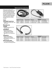
...8226; Site license for installation on and flexi-CT's are specially designed to work seamlessly with rollers Miscellaneous 1750/MC • Additional SD Memory Card for Fluke 1750 1750/SEAT-L • Fluke Power Analyze - Current Range 2 A to 100 A 20 A to 1000 A 100 A to 5000 A 100... 3.2 cm (1.25 in ) 5 Fluke Corporation Fluke 1750 Three-Phase Power Recorder Additional SEAT LICENSE • One additional license for installation on one additional PC 1750/SITE-L • Fluke Power Analyze - Optional Accessories Fluke power quality current transformers and flexible current probes ...
...8226; Site license for installation on and flexi-CT's are specially designed to work seamlessly with rollers Miscellaneous 1750/MC • Additional SD Memory Card for Fluke 1750 1750/SEAT-L • Fluke Power Analyze - Current Range 2 A to 100 A 20 A to 1000 A 100 A to 5000 A 100... 3.2 cm (1.25 in ) 5 Fluke Corporation Fluke 1750 Three-Phase Power Recorder Additional SEAT LICENSE • One additional license for installation on one additional PC 1750/SITE-L • Fluke Power Analyze - Optional Accessories Fluke power quality current transformers and flexible current probes ...
Fluke 1750 Three Phase Power Recorder Datasheet
Page 6
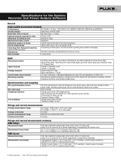
Specifications for the System: Recorder and Power Analyze Software General Power quality measurement standards Conformance IEC 61999-1-4 Class 1, IEC ...channels Input resistance: 2 MΩ Input capacitance: < 20 pF 2 V rms = full scale, 1 MΩ Input Impedance for ferro CTs, low impedance for delta power types. AC: ± 0.2 % reading ± 0.1 % full scale, above 50 V rms DC: ± 0.5 % reading ± 0.2 % full scale... for 5 % to the A-B voltage for Flexi-CTs Simultaneous digital sampling of current sensor range 6 Fluke Corporation Fluke 1750 Three-Phase Power Recorder
Specifications for the System: Recorder and Power Analyze Software General Power quality measurement standards Conformance IEC 61999-1-4 Class 1, IEC ...channels Input resistance: 2 MΩ Input capacitance: < 20 pF 2 V rms = full scale, 1 MΩ Input Impedance for ferro CTs, low impedance for delta power types. AC: ± 0.2 % reading ± 0.1 % full scale, above 50 V rms DC: ± 0.5 % reading ± 0.2 % full scale... for 5 % to the A-B voltage for Flexi-CTs Simultaneous digital sampling of current sensor range 6 Fluke Corporation Fluke 1750 Three-Phase Power Recorder
Fluke 1750 Three Phase Power Recorder Datasheet
Page 8
... V CAT IV (anticipated overvoltage: 8000 V) Ordering information Fluke-1750 Three-Phase Power Recorder Includes: • 1750 acquisition unit • PDA wireless "front panel interface" and charger power plug adapters • 4 - 400 A current probes (3140R) • 5 test leads and clips • SD memory card • Fluke Power View and Fluke Power Analyze software • Power cord with international plug set • Ethernet...
... V CAT IV (anticipated overvoltage: 8000 V) Ordering information Fluke-1750 Three-Phase Power Recorder Includes: • 1750 acquisition unit • PDA wireless "front panel interface" and charger power plug adapters • 4 - 400 A current probes (3140R) • 5 test leads and clips • SD memory card • Fluke Power View and Fluke Power Analyze software • Power cord with international plug set • Ethernet...
Fluke 1750 Calibration Manual
Page 3
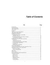
Table of Contents Title Page Introduction...1 Contacting Fluke 1 Safety Information 2 Symbols ...3 Specifications for the System: Recorder and Power Analyze Software 3 General Specifications 3 Input Specifications 3 Synchronization and Sampling 4 Voltage and Current Measurements 4 Voltage and Current Measurement Accuracy 4 Transient Voltage (Impulse 4 Dip (Sag) and Swell Measurements 4 Power and PF Measurement 5 External Interface Specifications 5 Environmental and Safety Specifications...
Table of Contents Title Page Introduction...1 Contacting Fluke 1 Safety Information 2 Symbols ...3 Specifications for the System: Recorder and Power Analyze Software 3 General Specifications 3 Input Specifications 3 Synchronization and Sampling 4 Voltage and Current Measurements 4 Voltage and Current Measurement Accuracy 4 Transient Voltage (Impulse 4 Dip (Sag) and Swell Measurements 4 Power and PF Measurement 5 External Interface Specifications 5 Environmental and Safety Specifications...

Fluke 1750 Calibration Manual
Page 11
... as an electricity meter or an overhead or underground utility service. See manual. Do not dispose of danger. Power Requirements 100 to Fluke's web site for Data At least 1 GB Maximum Recording Period At least 31 days Measurement Time Control Automatic ... and lighting systems in Table 1. Risk of the internal memory. Important information. Specifications for the System: Recorder and Power Analyze Software General Specifications Power Quality Measurement Standards Conformance IEC 61999-1-4 Class 1, IEC 61000-4-30 Class A or B depending on the Recorder are listed ...
... as an electricity meter or an overhead or underground utility service. See manual. Do not dispose of danger. Power Requirements 100 to Fluke's web site for Data At least 1 GB Maximum Recording Period At least 31 days Measurement Time Control Automatic ... and lighting systems in Table 1. Risk of the internal memory. Important information. Specifications for the System: Recorder and Power Analyze Software General Specifications Power Quality Measurement Standards Conformance IEC 61999-1-4 Class 1, IEC 61000-4-30 Class A or B depending on the Recorder are listed ...
Fluke 1750 Calibration Manual
Page 13
... for the System: Recorder and Power Analyze Software Measurement Accuracy Same as rms voltage Voltage Dip (RMS sag) Measurement Type True rms (one cycle calculation by overlapping each half cycle) (voltage between... orders: ± 0.5 % reading ± 0.2 % full scale 21st to 50th orders: ± 1 % reading ± 0.3 % full scale (current sensor accuracy must be included for current and power) Measurement Method IEC 61000-4-7 Inter-harmonic Voltage and Current (Intermediate Harmonics) Analysis Window rectangular Analysis Orders 0.5 to 49.5th order Measurement Method IEC 61000-4-7 External...
... for the System: Recorder and Power Analyze Software Measurement Accuracy Same as rms voltage Voltage Dip (RMS sag) Measurement Type True rms (one cycle calculation by overlapping each half cycle) (voltage between... orders: ± 0.5 % reading ± 0.2 % full scale 21st to 50th orders: ± 1 % reading ± 0.3 % full scale (current sensor accuracy must be included for current and power) Measurement Method IEC 61000-4-7 Inter-harmonic Voltage and Current (Intermediate Harmonics) Analysis Window rectangular Analysis Orders 0.5 to 49.5th order Measurement Method IEC 61000-4-7 External...
Fluke 1750 Calibration Manual
Page 14
...: 50 - 10000 Hz DC Voltage Range: 0 - 1000 V dc Accuracy: ± 0.03 % Ohms Range: 100 KΩ Accuracy: ± 0.011 % 1750 Cal Wizard and Fluke Power Analyze software installed Recommended Model Fluke 5520A Multi-Product Calibrator or equivalent Fluke 8846A Precision Multimeter or equivalent 6 Periodically wipe the case with 4-wire Ohms Personal Computer (PC) (Windows XP) Table 2. Equipment...
...: 50 - 10000 Hz DC Voltage Range: 0 - 1000 V dc Accuracy: ± 0.03 % Ohms Range: 100 KΩ Accuracy: ± 0.011 % 1750 Cal Wizard and Fluke Power Analyze software installed Recommended Model Fluke 5520A Multi-Product Calibrator or equivalent Fluke 8846A Precision Multimeter or equivalent 6 Periodically wipe the case with 4-wire Ohms Personal Computer (PC) (Windows XP) Table 2. Equipment...
Fluke 1750 Calibration Manual
Page 16
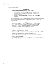
...to display the channels as L1, L2, and L3 instead of A, B, and C. Note Power Analyze can be needed. Connect an Ethernet cable to the Recorder. Select 1750 Live, then Scope. 6. 1750 Calibration Manual Verification Tests XWWarning To avoid electrical shock, personal injury, or fire: • ... only by qualified personnel. For this manual unless you are used to the Recorder front panel. Apply power to the Recorder. 2. For service, see Contacting Fluke. During power up, indicators near all the voltage display check boxes to do so. • Repairs or servicing should...
...to display the channels as L1, L2, and L3 instead of A, B, and C. Note Power Analyze can be needed. Connect an Ethernet cable to the Recorder. Select 1750 Live, then Scope. 6. 1750 Calibration Manual Verification Tests XWWarning To avoid electrical shock, personal injury, or fire: • ... only by qualified personnel. For this manual unless you are used to the Recorder front panel. Apply power to the Recorder. 2. For service, see Contacting Fluke. During power up, indicators near all the voltage display check boxes to do so. • Repairs or servicing should...
Fluke 1750 Calibration Manual
Page 17
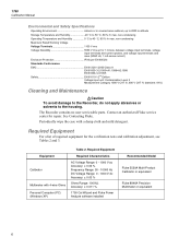
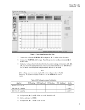
Power Recorder Verification Tests Figure 1. Connect the calibrator NORMAL HI to resize. Sine waves will be off . 9 AC Voltage Accuracy Verification AN Reading BN Reading CN ... scale, right click on the voltage scale on the left margin of the graphical display, then click on . Connect the NORMAL LO to STBY. 12. Power View Software Live View power analyze live view screen.bmp 7.
Power Recorder Verification Tests Figure 1. Connect the calibrator NORMAL HI to resize. Sine waves will be off . 9 AC Voltage Accuracy Verification AN Reading BN Reading CN ... scale, right click on the voltage scale on the left margin of the graphical display, then click on . Connect the NORMAL LO to STBY. 12. Power View Software Live View power analyze live view screen.bmp 7.

Fluke 1750 Calibration Manual
Page 20
1750 Calibration Manual Watt Verification 1. Impulse Verification Initialize the UUT XWWarning The impulse verification steps instruct the user to apply working voltages in Power Analyze. Power up the UUT and wait for approximately 15 seconds, and then disconnect. 15. Press OPR on the power button in ...start up, and connect with the numerical keypad and press Enter. Enter 90 with Power Analyze. 3. To avoid electrical shock or personal injury, DO NOT use connectors having exposed metal. 1. The power should be 0 ± 0.1 kW. Normalize Thresholds 4. Use the same connections as...
1750 Calibration Manual Watt Verification 1. Impulse Verification Initialize the UUT XWWarning The impulse verification steps instruct the user to apply working voltages in Power Analyze. Power up the UUT and wait for approximately 15 seconds, and then disconnect. 15. Press OPR on the power button in ...start up, and connect with the numerical keypad and press Enter. Enter 90 with Power Analyze. 3. To avoid electrical shock or personal injury, DO NOT use connectors having exposed metal. 1. The power should be 0 ± 0.1 kW. Normalize Thresholds 4. Use the same connections as...

Fluke 1750 Calibration Manual
Page 21
... four Volts selections are unchecked in Table 8. 33. Note, this can be most easily distinguished by the change in Table 8. 13 Click on 1750 Download, and then Save. 23. The following steps concern the two right-hand columns in any one of the Event Summary table. 30. Click... to Verify the Amplitude Accuracy of the Event Table until the AN Triggered Phase data is not used for Triggered Phase. 39. To Use Power Analyze to the bottom of Recorded Impulse Events 21. Click on View Recorded, and then Events. 24. Scroll down through the CN Triggered Phase ...
... four Volts selections are unchecked in Table 8. 33. Note, this can be most easily distinguished by the change in Table 8. 13 Click on 1750 Download, and then Save. 23. The following steps concern the two right-hand columns in any one of the Event Summary table. 30. Click... to Verify the Amplitude Accuracy of the Event Table until the AN Triggered Phase data is not used for Triggered Phase. 39. To Use Power Analyze to the bottom of Recorded Impulse Events 21. Click on View Recorded, and then Events. 24. Scroll down through the CN Triggered Phase ...
Fluke 1750 Operators Manual
Page 3
Table of Contents Title Page Introduction...1 Contacting Fluke 2 Safety Information 3 Accessories ...4 Features...5 Applying the Front Panel Decal 7 Charging the PDA Battery 9 Installing the Software 9 Installing Power View on the PDA 9 Language Selection 10 PC System Requirement for Power Analyze 10 Installing Power Analyze 10 Installing the Power Recorder at a Facility 11 Work Flow...11 Installing the Recorder 12...
Table of Contents Title Page Introduction...1 Contacting Fluke 2 Safety Information 3 Accessories ...4 Features...5 Applying the Front Panel Decal 7 Charging the PDA Battery 9 Installing the Software 9 Installing Power View on the PDA 9 Language Selection 10 PC System Requirement for Power Analyze 10 Installing Power Analyze 10 Installing the Power Recorder at a Facility 11 Work Flow...11 Installing the Recorder 12...
Fluke 1750 Operators Manual
Page 4
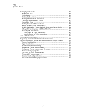
1750 Operators Manual Setting Up the Recorder 38 Setting the Clock 40 Probe Detect 40 Setting the IP Address 41 Adding a Measurement Description 41 Configure Nominal Power Values 42 Using Phase Swap 42 Setting the Volts and Current Ratio 43 Assign Recorder Name ...off the Recorder 48 Cleaning and Maintenance 48 Regulatory Information for Wireless Communication 49 Specifications for the System: Recorder and Power Analyze Software 50 General Specifications 50 Input Specifications 50 Synchronization and Sampling 50 Voltage and Current Measurements 50 Voltage and Current Measurement...
1750 Operators Manual Setting Up the Recorder 38 Setting the Clock 40 Probe Detect 40 Setting the IP Address 41 Adding a Measurement Description 41 Configure Nominal Power Values 42 Using Phase Swap 42 Setting the Volts and Current Ratio 43 Assign Recorder Name ...off the Recorder 48 Cleaning and Maintenance 48 Regulatory Information for Wireless Communication 49 Specifications for the System: Recorder and Power Analyze Software 50 General Specifications 50 Input Specifications 50 Synchronization and Sampling 50 Voltage and Current Measurements 50 Voltage and Current Measurement...

Fluke 1750 Operators Manual
Page 9
... the recorded data. The 1750 Power Recorder, referred to hereafter as simply "the Recorder or the Product," consists of flexible and clamp-on each phase that you do not need a PC to use PC application, Power Analyze. A wide range of a power recorder instrument, a wireless ...Simplified test lead connections to the power network Simply connect a voltage probe to a conductor on current probes are provided as a controller, you want to the PDA. 1750 Power Recorder Introduction The Fluke 1750 Power Recorder is about 5 meters (16 feet) from Fluke. Four 400 A current probes are...
... the recorded data. The 1750 Power Recorder, referred to hereafter as simply "the Recorder or the Product," consists of flexible and clamp-on each phase that you do not need a PC to use PC application, Power Analyze. A wide range of a power recorder instrument, a wireless ...Simplified test lead connections to the power network Simply connect a voltage probe to a conductor on current probes are provided as a controller, you want to the PDA. 1750 Power Recorder Introduction The Fluke 1750 Power Recorder is about 5 meters (16 feet) from Fluke. Four 400 A current probes are...
Fluke 1750 Operators Manual
Page 10
...: 1-888-99-FLUKE (1-888-993-5853) • Canada: 1-800-36-FLUKE (1-800-363-5853) • Europe: +31 402-675-200 • Japan: +81-3-3434-0181 • Singapore: +65-738-5655 • Anywhere in the software. Data may then be analyzed using the Power Analyze software on the ...1750 Operators Manual • Automatic disturbance capture The Recorder uses an automatic, self-learning threshold routine, which means you do not have to set up and start recording. With these features, there is stored on a PC. You detect and display power quality events (disturbances) using Power Analyze...
...: 1-888-99-FLUKE (1-888-993-5853) • Canada: 1-800-36-FLUKE (1-800-363-5853) • Europe: +31 402-675-200 • Japan: +81-3-3434-0181 • Singapore: +65-738-5655 • Anywhere in the software. Data may then be analyzed using the Power Analyze software on the ...1750 Operators Manual • Automatic disturbance capture The Recorder uses an automatic, self-learning threshold routine, which means you do not have to set up and start recording. With these features, there is stored on a PC. You detect and display power quality events (disturbances) using Power Analyze...
Fluke 1750 Operators Manual
Page 17
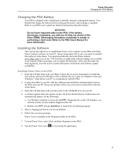
... to your PDA. After your PC to reinstall this software in the future. Connect the PDA to install Fluke Power View software on the PDA and Fluke Power Analyze software on your product CD in case you need to communicate with a discharged or partially charged, rechargeable battery.... Use Windows Explorer to performing a hard reset. Replace x.yy with your Recorder in the CD-ROM drive on your product CD in case you need to see if any 1750...
... to your PDA. After your PC to reinstall this software in the future. Connect the PDA to install Fluke Power View software on the PDA and Fluke Power Analyze software on your product CD in case you need to communicate with a discharged or partially charged, rechargeable battery.... Use Windows Explorer to performing a hard reset. Replace x.yy with your Recorder in the CD-ROM drive on your product CD in case you need to see if any 1750...

Fluke 1750 Operators Manual
Page 18
... of available disk space, 10 GB recommended). • 1024 x 768 or higher resolution video. • Keyboard and mouse. Installing Power Analyze Before installing the software on a new PDA or after you have successfully installed the software, rebooted the machine, and opened the application.... 1. This window is also accessed by Menu>1750 Setup>Language. 1750 Operators Manual Language Selection Power View features a localized user interface for Power Analyze • Windows 2000, Windows XP, Windows Vista 32/64bit, Windows 7 32/64bit.
... of available disk space, 10 GB recommended). • 1024 x 768 or higher resolution video. • Keyboard and mouse. Installing Power Analyze Before installing the software on a new PDA or after you have successfully installed the software, rebooted the machine, and opened the application.... 1. This window is also accessed by Menu>1750 Setup>Language. 1750 Operators Manual Language Selection Power View features a localized user interface for Power Analyze • Windows 2000, Windows XP, Windows Vista 32/64bit, Windows 7 32/64bit.
Fluke 1750 Operators Manual
Page 19
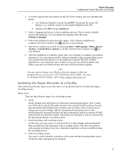
... the number provided on the form. You can change your desktop. 6. Start Power Analyze on your PC by choosing Start >All Programs >Fluke >Power Analyze >Launch Power Analyze or double-click the Power Analyze icon on your Windows firewall settings to allow the program FPA.exe to use...since the beginning of connections and measured signals. Power Analyze initially starts in any recorder settings. Follow the installation instructions that lists options on the CD. Power Recorder Installing the Power Recorder at http://register.fluke.com or you can print the form and fax...
... the number provided on the form. You can change your desktop. 6. Start Power Analyze on your PC by choosing Start >All Programs >Fluke >Power Analyze >Launch Power Analyze or double-click the Power Analyze icon on your Windows firewall settings to allow the program FPA.exe to use...since the beginning of connections and measured signals. Power Analyze initially starts in any recorder settings. Follow the installation instructions that lists options on the CD. Power Recorder Installing the Power Recorder at http://register.fluke.com or you can print the form and fax...


