Fluke 1750 Three Phase Power Recorder Datasheet
Page 2
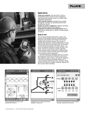
... you. 2 Fluke Corporation Fluke 1750 Three-Phase Power Recorder No need to control multiple instruments from a distance easily, without the need for a laptop computer (laptops can also be used when desired). monitor critical equipment, capturing power quality events to correlate with equipment malfunction Power quality surveys: Quantify power quality throughout a facility, documenting results with waveform displays, meter screens...
... you. 2 Fluke Corporation Fluke 1750 Three-Phase Power Recorder No need to control multiple instruments from a distance easily, without the need for a laptop computer (laptops can also be used when desired). monitor critical equipment, capturing power quality events to correlate with equipment malfunction Power quality surveys: Quantify power quality throughout a facility, documenting results with waveform displays, meter screens...
Fluke 1750 Three Phase Power Recorder Datasheet
Page 3
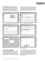
...Full FFT on each channel and totals. card without compression or overwriting. Events can be made . 3 Fluke Corporation Fluke 1750 Three-Phase Power Recorder Full-featured power meter display for the EN50160 report are easily customized. Data is retrieved via the PDA to flag important points ... computer via Ethernet, using your recorded data when a transfer switch was operated, or load changes were made via one graph. Powerful data management Data is automatically stored on all input channels simultaneously, no matter which channel triggered the event. Imagine being able to...
...Full FFT on each channel and totals. card without compression or overwriting. Events can be made . 3 Fluke Corporation Fluke 1750 Three-Phase Power Recorder Full-featured power meter display for the EN50160 report are easily customized. Data is retrieved via the PDA to flag important points ... computer via Ethernet, using your recorded data when a transfer switch was operated, or load changes were made via one graph. Powerful data management Data is automatically stored on all input channels simultaneously, no matter which channel triggered the event. Imagine being able to...

Fluke 1750 Calibration Manual
Page 11
...Power Analyze Software General Specifications Power Quality Measurement Standards Conformance IEC 61999-1-4 Class 1, IEC 61000-4-30 Class A or B depending on the Recorder are listed in Table 1. CAT IV CAT IV equipment is designed to protect against transients in equipment in fixedequipment installations, such as an electricity meter...branch circuits, and lighting systems in large buildings. Protective conductor terminal. Table 1. See manual. Power Requirements 100 to Fluke's web site for Data At least 1 GB Maximum Recording Period At least 31 days Measurement ...
...Power Analyze Software General Specifications Power Quality Measurement Standards Conformance IEC 61999-1-4 Class 1, IEC 61000-4-30 Class A or B depending on the Recorder are listed in Table 1. CAT IV CAT IV equipment is designed to protect against transients in equipment in fixedequipment installations, such as an electricity meter...branch circuits, and lighting systems in large buildings. Protective conductor terminal. Table 1. See manual. Power Requirements 100 to Fluke's web site for Data At least 1 GB Maximum Recording Period At least 31 days Measurement ...
Fluke 1750 Operators Manual
Page 3
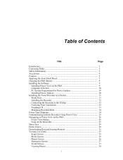
...Page Introduction...1 Contacting Fluke 2 Safety Information 3 Accessories ...4 Features...5 Applying the Front Panel Decal 7 Charging the PDA Battery 9 Installing the Software 9 Installing Power View on the PDA 9 Language Selection 10 PC System Requirement for Power Analyze 10 Installing Power Analyze 10 Installing the Power Recorder at a Facility... Using Power View 25 Navigating in Power View on the PDA 26 Power View Menus 26 Icons on the Menu Bar 27 Menu Tree...28 Home Screen...29 Downloading Data and Erasing Memory 31 Viewing Live Data 35 Scope Screen 35 Meter Screen ...
...Page Introduction...1 Contacting Fluke 2 Safety Information 3 Accessories ...4 Features...5 Applying the Front Panel Decal 7 Charging the PDA Battery 9 Installing the Software 9 Installing Power View on the PDA 9 Language Selection 10 PC System Requirement for Power Analyze 10 Installing Power Analyze 10 Installing the Power Recorder at a Facility... Using Power View 25 Navigating in Power View on the PDA 26 Power View Menus 26 Icons on the Menu Bar 27 Menu Tree...28 Home Screen...29 Downloading Data and Erasing Memory 31 Viewing Live Data 35 Scope Screen 35 Meter Screen ...

Fluke 1750 Operators Manual
Page 9
1750 Power Recorder Introduction The Fluke 1750 Power Recorder is a comprehensive yet easy to the PDA. A wide range of the 1750 Power Recorder are using the PDA, and then reconfirm correct readings. • Internal Uninterruptible Power Supply (UPS) An internal NiMH (Nickel-Metal-Hydride) battery pack and charging system maintain data capture continuity through power... with the wireless link is about 5 meters (16 feet) from Fluke. The Recorder then configures its measurement system appropriately for control and setup, and a powerful yet easy to hereafter as standard equipment ...
1750 Power Recorder Introduction The Fluke 1750 Power Recorder is a comprehensive yet easy to the PDA. A wide range of the 1750 Power Recorder are using the PDA, and then reconfirm correct readings. • Internal Uninterruptible Power Supply (UPS) An internal NiMH (Nickel-Metal-Hydride) battery pack and charging system maintain data capture continuity through power... with the wireless link is about 5 meters (16 feet) from Fluke. The Recorder then configures its measurement system appropriately for control and setup, and a powerful yet easy to hereafter as standard equipment ...
Fluke 1750 Operators Manual
Page 12
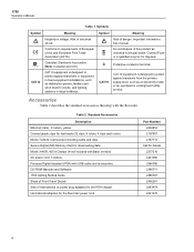
1750 Operators Manual Table 1. Symbol W ~ J CAT IV Meaning Risk of electrical shock. Table 2. Symbols Symbol X P ) CAT III Meaning Hazardous voltage. Risk of danger. See manual. Contact Fluke or a qualified recycler for downloading data Model 3140R, 400 A Clamps (4-not included with Basic version) AC power cord, 3 meters Personal Digital Assistant (PDA) with the Recorder. Protective conductor...
1750 Operators Manual Table 1. Symbol W ~ J CAT IV Meaning Risk of electrical shock. Table 2. Symbols Symbol X P ) CAT III Meaning Hazardous voltage. Risk of danger. See manual. Contact Fluke or a qualified recycler for downloading data Model 3140R, 400 A Clamps (4-not included with Basic version) AC power cord, 3 meters Personal Digital Assistant (PDA) with the Recorder. Protective conductor...

Fluke 1750 Operators Manual
Page 31
ØA/L1 ØC/L3 ØB/L2 GND Power Recorder Power Type Diagrams A/L1 GND B/L2 C/L3 POWER 1750 POWER RECORDER VOLTAGE A B C N 100-240 V 47-63Hz ON CURRENT SD ETHERNET LINK BUSY Figure 12. 2-Element Delta azd13f.eps Example: Blondel or Aron connection, used to measure power like a two-element revenue power meter. 23
ØA/L1 ØC/L3 ØB/L2 GND Power Recorder Power Type Diagrams A/L1 GND B/L2 C/L3 POWER 1750 POWER RECORDER VOLTAGE A B C N 100-240 V 47-63Hz ON CURRENT SD ETHERNET LINK BUSY Figure 12. 2-Element Delta azd13f.eps Example: Blondel or Aron connection, used to measure power like a two-element revenue power meter. 23

Fluke 1750 Operators Manual
Page 34
...Power View Menus Live Brings up the setup screen that allows you to quickly and easily configure a Recorder, view live data, and transfer data to the Secure Data (SD) card for erasing Recorder internal memory and erasing SD card files. 1750 Setup Brings up a list of the live detail views: Scope, Meter... of each type of screen available by tapping the sector of interest or the Live menu. 1750 Operators Manual Navigating in the Recorder and for viewing and analysis on the bottom of the Power View screen allows you to configure the Recorder and set the following: • Clock •...
...Power View Menus Live Brings up the setup screen that allows you to quickly and easily configure a Recorder, view live data, and transfer data to the Secure Data (SD) card for erasing Recorder internal memory and erasing SD card files. 1750 Setup Brings up a list of the live detail views: Scope, Meter... of each type of screen available by tapping the sector of interest or the Live menu. 1750 Operators Manual Navigating in the Recorder and for viewing and analysis on the bottom of the Power View screen allows you to configure the Recorder and set the following: • Clock •...

Fluke 1750 Operators Manual
Page 36
... Tree The following figure provides an overview of the Power View menu structure that will be helpful in navigating through the Power View application. Erase 1750 Memory Fluke Power View 1750 Power Recorders Found Connecting 1750 Power Recorder Not Found Live Scope Meter Phasor Harmonics Trend Home Menu Tools 1750 Setup Exit 1750 Download Write to SD SD Card Files Scope If...
... Tree The following figure provides an overview of the Power View menu structure that will be helpful in navigating through the Power View application. Erase 1750 Memory Fluke Power View 1750 Power Recorders Found Connecting 1750 Power Recorder Not Found Live Scope Meter Phasor Harmonics Trend Home Menu Tools 1750 Setup Exit 1750 Download Write to SD SD Card Files Scope If...

Fluke 1750 Operators Manual
Page 37
The parameters shown in this screen are shown simultaneously, either all voltage or all current. Power Recorder Home Screen Home Screen The Home screen is the top-level screen, accessed when you start Power View or when you tap Live and then Home on the Menu Bar. All phases are not configurable. If no Recorders are within range, the following screen appears: Azd111.bmp Azd112.bmp 29 The Home screen contains a 1.5 cycle waveform screen, a digital meter screen, and a PHASOR screen.
The parameters shown in this screen are shown simultaneously, either all voltage or all current. Power Recorder Home Screen Home Screen The Home screen is the top-level screen, accessed when you start Power View or when you tap Live and then Home on the Menu Bar. All phases are not configurable. If no Recorders are within range, the following screen appears: Azd111.bmp Azd112.bmp 29 The Home screen contains a 1.5 cycle waveform screen, a digital meter screen, and a PHASOR screen.

Fluke 1750 Operators Manual
Page 43
Azd121.bmp 35 Tap the Phase icon ( ) to view live data on the circuits on the circuits for the volts and amp lines selected in the check boxes on Phase View screen. Power Recorder Viewing Live Data Viewing Live Data The Live menu is used to display the Phase View screen. Azd120.bmp Scope Screen The Scope screen shows 1.5 cycle waveform data for example, Scope, Meter, Phasor, or Harmonics.
Azd121.bmp 35 Tap the Phase icon ( ) to view live data on the circuits on the circuits for the volts and amp lines selected in the check boxes on Phase View screen. Power Recorder Viewing Live Data Viewing Live Data The Live menu is used to display the Phase View screen. Azd120.bmp Scope Screen The Scope screen shows 1.5 cycle waveform data for example, Scope, Meter, Phasor, or Harmonics.

Fluke 1750 Operators Manual
Page 51
Power Recorder Setting Up the Recorder Azd133.bmp Setting the Volts and Current Ratio Use this feature to assign a name identifier to the Recorder and to ... present on each case if there is a potential transformer in series with the data file that has built-in use. This naming feature is in metering current transformers. Changing the first "1" in order to the voltage or current input on a medium-voltage network.
Power Recorder Setting Up the Recorder Azd133.bmp Setting the Volts and Current Ratio Use this feature to assign a name identifier to the Recorder and to ... present on each case if there is a potential transformer in series with the data file that has built-in use. This naming feature is in metering current transformers. Changing the first "1" in order to the voltage or current input on a medium-voltage network.


