
Fluke 1750 Three Phase Power Recorder Datasheet
Page 1
... Easily analyze data and generate reports. less "front panel interface" provides the ability to reconnect wires: Swap channels internally with the Fluke 1750 Power Recorder. Capture every measurement, every event, on three phases, neutral, and ground. • 5 MHz, 8000 Vpk waveform capture: ... • Quickly retrieve data: With included SD memory card or via the 100BaseT high-speed Ethernet connection. Fluke 1750 Three-Phase Power Recorder Technical Data Never miss capturing a disturbance-with self- Outstanding accuracy and resolution provide complete visibility into what the...
... Easily analyze data and generate reports. less "front panel interface" provides the ability to reconnect wires: Swap channels internally with the Fluke 1750 Power Recorder. Capture every measurement, every event, on three phases, neutral, and ground. • 5 MHz, 8000 Vpk waveform capture: ... • Quickly retrieve data: With included SD memory card or via the 100BaseT high-speed Ethernet connection. Fluke 1750 Three-Phase Power Recorder Technical Data Never miss capturing a disturbance-with self- Outstanding accuracy and resolution provide complete visibility into what the...
Fluke 1750 Three Phase Power Recorder Datasheet
Page 2
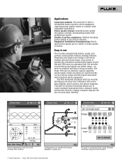
...-lead voltage connections enables safe and quick setups. no more uncertainty that the recorder is being recorded. View measurements real-time with waveform displays, meter screens, and phasor diagrams. The built-in wireless technology allows you . 2 Fluke Corporation Fluke 1750 Three-Phase Power Recorder No need for a laptop computer (laptops can also be used when desired). The...
...-lead voltage connections enables safe and quick setups. no more uncertainty that the recorder is being recorded. View measurements real-time with waveform displays, meter screens, and phasor diagrams. The built-in wireless technology allows you . 2 Fluke Corporation Fluke 1750 Three-Phase Power Recorder No need for a laptop computer (laptops can also be used when desired). The...
Fluke 1750 Three Phase Power Recorder Datasheet
Page 3
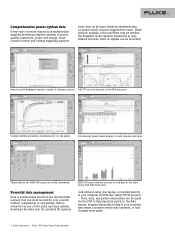
... simultaneously sampled providing complete analysis of tolerance curves. Events can be displayed against a variety of power quality, harmonics, power and energy. Display multiple parameters simultaneously on one of the waveform may be made . 3 Fluke Corporation Fluke 1750 Three-Phase Power Recorder Data is automatically stored on each channel and totals. Thresholds for each channel to flag important...
... simultaneously sampled providing complete analysis of tolerance curves. Events can be displayed against a variety of power quality, harmonics, power and energy. Display multiple parameters simultaneously on one of the waveform may be made . 3 Fluke Corporation Fluke 1750 Three-Phase Power Recorder Data is automatically stored on each channel and totals. Thresholds for each channel to flag important...
Fluke 1750 Three Phase Power Recorder Datasheet
Page 4
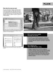
...and, therefore, can be used for most power connections and for all outlets in a low-voltage power distribution system. 4 Fluke Corporation Fluke 1750 Three-Phase Power Recorder Apply thresholds to data after the data is recorded! All the latest power quality standards are built-in IEC 61000-4-...CAT IV and 1000 V CAT III safety rating Designed to help protect you want The new Fluke Power Analyze software revolutionizes your equipment, the Fluke 1750 Three-Phase Power Recorder and accessories are all parameters are the first tools of standard or customized templates. View data ...
...and, therefore, can be used for most power connections and for all outlets in a low-voltage power distribution system. 4 Fluke Corporation Fluke 1750 Three-Phase Power Recorder Apply thresholds to data after the data is recorded! All the latest power quality standards are built-in IEC 61000-4-...CAT IV and 1000 V CAT III safety rating Designed to help protect you want The new Fluke Power Analyze software revolutionizes your equipment, the Fluke 1750 Three-Phase Power Recorder and accessories are all parameters are the first tools of standard or customized templates. View data ...
Fluke 1750 Three Phase Power Recorder Datasheet
Page 5
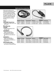
... ft) looped lockable steel cable for Fluke 1750 1750/SEAT-L • Fluke Power Analyze - All clamp-on and flexi-CT's are specially designed to work seamlessly with rollers Miscellaneous 1750/MC • Additional SD Memory Card...Fluke power monitors (1750 and 1650). Current Range 2 A to 100 A 20 A to 1000 A 100 A to 5000 A 100 A to 400 A Accuracy 1 % RDG ± 0.5 % FS 1 % RDG ± 0.1 % FS 2 % RDG ± 0.04 A Frequency Response 5 kHz 5 kHz 20 kHz Jaw Opening 2 cm (.78 in) dia. 2 cm (.78 in) dia. 3.2 cm (1.25 in ) 5 Fluke Corporation Fluke 1750 Three-Phase Power Recorder...
... ft) looped lockable steel cable for Fluke 1750 1750/SEAT-L • Fluke Power Analyze - All clamp-on and flexi-CT's are specially designed to work seamlessly with rollers Miscellaneous 1750/MC • Additional SD Memory Card...Fluke power monitors (1750 and 1650). Current Range 2 A to 100 A 20 A to 1000 A 100 A to 5000 A 100 A to 400 A Accuracy 1 % RDG ± 0.5 % FS 1 % RDG ± 0.1 % FS 2 % RDG ± 0.04 A Frequency Response 5 kHz 5 kHz 20 kHz Jaw Opening 2 cm (.78 in) dia. 2 cm (.78 in) dia. 3.2 cm (1.25 in ) 5 Fluke Corporation Fluke 1750 Three-Phase Power Recorder...
Fluke 1750 Three Phase Power Recorder Datasheet
Page 6
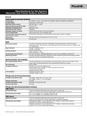
... scale, 1 MΩ Input Impedance for ferro CTs, low impedance for Flexi-CTs Simultaneous digital sampling of current sensor range 6 Fluke Corporation Fluke 1750 Three-Phase Power Recorder Specifications for the System: Recorder and Power Analyze Software General Power quality measurement standards Conformance IEC 61999-1-4 Class 1, IEC 61000-4-30, IEEE519, IEEE1159, IEEE1459 and EN50160 Clock/calendar Leap years, 24...
... scale, 1 MΩ Input Impedance for ferro CTs, low impedance for Flexi-CTs Simultaneous digital sampling of current sensor range 6 Fluke Corporation Fluke 1750 Three-Phase Power Recorder Specifications for the System: Recorder and Power Analyze Software General Power quality measurement standards Conformance IEC 61999-1-4 Class 1, IEC 61000-4-30, IEEE519, IEEE1159, IEEE1459 and EN50160 Clock/calendar Leap years, 24...
Fluke 1750 Three Phase Power Recorder Datasheet
Page 7
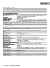
... sequence voltage divided by negative sequence voltage, per EN 61000-4-15:2003: 10 min (Pst), 2 h (Plt) 7 Fluke Corporation Fluke 1750 Three-Phase Power Recorder Transient voltage (impulse) Measurement type Full scale Sample resolution Measurement uncertainty Waveshape sampling 8000 V pk 200 nS ± 5 ... standards Measurement accuracy +/- (voltage uncertainty + current uncertainty + current probe uncertainty) Frequency Measurement range Measurement source Measurement accuracy Power factor 42.5 to 69 Hz Same as PLL synchronization source ± 10 mHz (10 to 110 % of range,...
... sequence voltage divided by negative sequence voltage, per EN 61000-4-15:2003: 10 min (Pst), 2 h (Plt) 7 Fluke Corporation Fluke 1750 Three-Phase Power Recorder Transient voltage (impulse) Measurement type Full scale Sample resolution Measurement uncertainty Waveshape sampling 8000 V pk 200 nS ± 5 ... standards Measurement accuracy +/- (voltage uncertainty + current uncertainty + current probe uncertainty) Frequency Measurement range Measurement source Measurement accuracy Power factor 42.5 to 69 Hz Same as PLL synchronization source ± 10 mHz (10 to 110 % of range,...
Fluke 1750 Three Phase Power Recorder Datasheet
Page 8
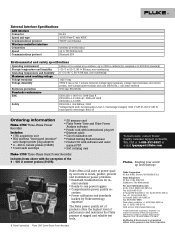
...; 2000 Voltage input unit: Contamination Level 2, Overvoltage Category 1000 V CAT III, 600 V CAT IV (anticipated overvoltage: 8000 V) Ordering information Fluke-1750 Three-Phase Power Recorder Includes: • 1750 acquisition unit • PDA wireless "front panel interface" and charger power plug adapters • 4 - 400 A current probes (3140R) • 5 test leads and clips • SD memory card •...
...; 2000 Voltage input unit: Contamination Level 2, Overvoltage Category 1000 V CAT III, 600 V CAT IV (anticipated overvoltage: 8000 V) Ordering information Fluke-1750 Three-Phase Power Recorder Includes: • 1750 acquisition unit • PDA wireless "front panel interface" and charger power plug adapters • 4 - 400 A current probes (3140R) • 5 test leads and clips • SD memory card •...

Fluke 1750 Calibration Manual
Page 1
All product names are subject to change without notice. Product specifications are trademarks of their respective companies. ® 1750 Power Recorder Calibration Manual November 2007 Rev. 1, 12/08 © 2007-2008 Fuke Corporation, All rights reserved.
All product names are subject to change without notice. Product specifications are trademarks of their respective companies. ® 1750 Power Recorder Calibration Manual November 2007 Rev. 1, 12/08 © 2007-2008 Fuke Corporation, All rights reserved.
Fluke 1750 Calibration Manual
Page 9
...so. Contacting Fluke To contact Fluke, call: 1-888-993-5853 in USA 1-800-363-5853 in Canada +31-402-675-200 in Europe +81-3-3434-0181 in Japan +65-738-5655 in Singapore +1-425-446-5500 from anywhere in this manual unless you are qualified to the 1750 Users Manual CD.... The information provided in the world Or, visit Fluke's Web site at www.fluke.com To register your product, visit http://register.fluke.com 1 1750 Power Recorder Introduction XW Warning To avoid electric shock or personal injury, do ...
...so. Contacting Fluke To contact Fluke, call: 1-888-993-5853 in USA 1-800-363-5853 in Canada +31-402-675-200 in Europe +81-3-3434-0181 in Japan +65-738-5655 in Singapore +1-425-446-5500 from anywhere in this manual unless you are qualified to the 1750 Users Manual CD.... The information provided in the world Or, visit Fluke's Web site at www.fluke.com To register your product, visit http://register.fluke.com 1 1750 Power Recorder Introduction XW Warning To avoid electric shock or personal injury, do ...

Fluke 1750 Calibration Manual
Page 10
... in this manual, or the protection provided by the Recorder may be impaired. 2 1750 Calibration Manual To contact Technical Support: fpqsupport@fluke.com or 888-257-9897 (US only) Safety Information The 1750 Power Recorder (hereafter referred to as the Recorder) complies with the Recorder, or indicated as suitable for the Recorder. • Before use . • Make sure the...
... in this manual, or the protection provided by the Recorder may be impaired. 2 1750 Calibration Manual To contact Technical Support: fpqsupport@fluke.com or 888-257-9897 (US only) Safety Information The 1750 Power Recorder (hereafter referred to as the Recorder) complies with the Recorder, or indicated as suitable for the Recorder. • Before use . • Make sure the...

Fluke 1750 Calibration Manual
Page 11
Do not dispose of danger. Go to Fluke's web site for Data At least 1 GB Maximum Recording Period At least 31 days Measurement Time Control Automatic Maximum Number of Events Limited only by the size of the internal memory. ... 100 to protect against transients in equipment in fixedequipment installations, such as an electricity meter or an overhead or underground utility service. See manual. Power Recorder Symbols Symbols Symbols used in this product as unsorted ~ municipal waste. Risk of European P Union and European Free Trade Association (EFTA). ) Canadian ...
Do not dispose of danger. Go to Fluke's web site for Data At least 1 GB Maximum Recording Period At least 31 days Measurement Time Control Automatic Maximum Number of Events Limited only by the size of the internal memory. ... 100 to protect against transients in equipment in fixedequipment installations, such as an electricity meter or an overhead or underground utility service. See manual. Power Recorder Symbols Symbols Symbols used in this product as unsorted ~ municipal waste. Risk of European P Union and European Free Trade Association (EFTA). ) Canadian ...
Fluke 1750 Calibration Manual
Page 13
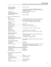
Power Recorder Specifications for the System: Recorder and Power Analyze Software Measurement Accuracy Same as rms voltage Voltage Dip (RMS sag) Measurement Type True rms (one cycle calculation by overlapping each half ...± 0.5 % reading ± 0.2 % full scale 21st to 50th orders: ± 1 % reading ± 0.3 % full scale (current sensor accuracy must be included for current and power) Measurement Method IEC 61000-4-7 Inter-harmonic Voltage and Current (Intermediate Harmonics) Analysis Window rectangular Analysis Orders 0.5 to 49.5th order Measurement Method IEC 61000-4-7 External...
Power Recorder Specifications for the System: Recorder and Power Analyze Software Measurement Accuracy Same as rms voltage Voltage Dip (RMS sag) Measurement Type True rms (one cycle calculation by overlapping each half ...± 0.5 % reading ± 0.2 % full scale 21st to 50th orders: ± 1 % reading ± 0.3 % full scale (current sensor accuracy must be included for current and power) Measurement Method IEC 61000-4-7 Inter-harmonic Voltage and Current (Intermediate Harmonics) Analysis Window rectangular Analysis Orders 0.5 to 49.5th order Measurement Method IEC 61000-4-7 External...
Fluke 1750 Calibration Manual
Page 15
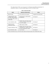
Required Cables Required Characteristics Notes Ethernet cable CAT 5 with RJ-45 connectors Supplied with the Recorder Voltage calibration cable with BNC-banana adapter Double banana to safety banana and spade lug See Figure 5 Four jumper cables, safetybanana ...to banana See Figure 2 Fluke recommends the use of Pomona brand cables and banana plugs when building these cables. 7 Cable Table 3. To assemble the cables, see cable assembly figures in Redel connector with double banana to Rogowski pins in the Test Cables section. Power Recorder Required Equipment The cables listed...
Required Cables Required Characteristics Notes Ethernet cable CAT 5 with RJ-45 connectors Supplied with the Recorder Voltage calibration cable with BNC-banana adapter Double banana to safety banana and spade lug See Figure 5 Four jumper cables, safetybanana ...to banana See Figure 2 Fluke recommends the use of Pomona brand cables and banana plugs when building these cables. 7 Cable Table 3. To assemble the cables, see cable assembly figures in Redel connector with double banana to Rogowski pins in the Test Cables section. Power Recorder Required Equipment The cables listed...
Fluke 1750 Calibration Manual
Page 17
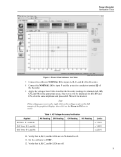
...10. Verify that A, B, C, and J LEDs are on the Zoom to Fit box to input N and the protective conductor terminal . of the Recorder. 8. Note If the voltage goes over scale, right click on the voltage scale on the left margin of the graphical display, then click on ...11. Power View Software Live View power analyze live view screen.bmp 7. Apply the voltages from Table 4 and list the Recorder readings for AN, BN and CN, all at the same amplitude and phase shift. N should be inverted. Set the calibrator to inputs A, B, C, and J of the Recorder. 9. Power Recorder Verification Tests...
...10. Verify that A, B, C, and J LEDs are on the Zoom to Fit box to input N and the protective conductor terminal . of the Recorder. 8. Note If the voltage goes over scale, right click on the voltage scale on the left margin of the graphical display, then click on ...11. Power View Software Live View power analyze live view screen.bmp 7. Apply the voltages from Table 4 and list the Recorder readings for AN, BN and CN, all at the same amplitude and phase shift. N should be inverted. Set the calibrator to inputs A, B, C, and J of the Recorder. 9. Power Recorder Verification Tests...

Fluke 1750 Calibration Manual
Page 19
... B Reading C Reading N Reading G Reading Limits ± 0.20 A ± 0.35 A ± 0.60 A 9. The current test calibration cable connects the voltage to voltages from Table 7 on the Recorder. 3. Press OPR. 8. Applied Voltage Expected Reading 0.4 V 20 A 1.0 V 50 A 2.0 V 100 A Table 7. Connect the calibrator NORMAL HI to Voltage N and J on the AUX output. 5.... Verification 1. ensure the HARMONIC selection is set to 1 and the FUNDMTL selection is 0.0 °. 6. Connect the calibrator AUX HI and LO to aux. 7. Power Recorder Verification Tests Table 6. See Figure 6.
... B Reading C Reading N Reading G Reading Limits ± 0.20 A ± 0.35 A ± 0.60 A 9. The current test calibration cable connects the voltage to voltages from Table 7 on the Recorder. 3. Press OPR. 8. Applied Voltage Expected Reading 0.4 V 20 A 1.0 V 50 A 2.0 V 100 A Table 7. Connect the calibrator NORMAL HI to Voltage N and J on the AUX output. 5.... Verification 1. ensure the HARMONIC selection is set to 1 and the FUNDMTL selection is 0.0 °. 6. Connect the calibrator AUX HI and LO to aux. 7. Power Recorder Verification Tests Table 6. See Figure 6.

Fluke 1750 Calibration Manual
Page 21
... data until G-triggered data is reached. Scroll down through the N-triggered data until N-triggered data is reached. Power Recorder Verification Tests 17. Press STBY on Event Detector. 26. To Use Power Analyze to 0 V 0 Hz. Click Done. 28. These will all channels the same and set both ...the calibrator to -last N-triggered Phase Absolute value in the Event Summary table, the Absolute and Triggered Phase columns. 31. Click on 1750 Download, and then Save. 23. Starting from the CN Triggered Phase data. Scroll down the table through the BN Triggered Phase data ...
... data until G-triggered data is reached. Scroll down through the N-triggered data until N-triggered data is reached. Power Recorder Verification Tests 17. Press STBY on Event Detector. 26. To Use Power Analyze to 0 V 0 Hz. Click Done. 28. These will all channels the same and set both ...the calibrator to -last N-triggered Phase Absolute value in the Event Summary table, the Absolute and Triggered Phase columns. 31. Click on 1750 Download, and then Save. 23. Starting from the CN Triggered Phase data. Scroll down the table through the BN Triggered Phase data ...
Fluke 1750 Calibration Manual
Page 23
...the PC to be returned for inspection and service. This will shut down and restart using the new calibration values. See Contacting Fluke. 9. Power Recorder Calibration Calibration is password protected, the correct password must be calibrated, and then click Connect. This may take up (30 ..., setting the correct sources, and finalizing the calibration. Cal Wizard steps through the calibration procedure, with instructions for the Recorder). Reset the calibrator. This can either be by 1750 Cal Wizard Software (Cal Wizard), which communicates with an Ethernet cable.
...the PC to be returned for inspection and service. This will shut down and restart using the new calibration values. See Contacting Fluke. 9. Power Recorder Calibration Calibration is password protected, the correct password must be calibrated, and then click Connect. This may take up (30 ..., setting the correct sources, and finalizing the calibration. Cal Wizard steps through the calibration procedure, with instructions for the Recorder). Reset the calibrator. This can either be by 1750 Cal Wizard Software (Cal Wizard), which communicates with an Ethernet cable.

Fluke 1750 Calibration Manual
Page 27
Voltage Calibration Cable fdo03.eps 19 Power Recorder Test Cables Figure 5.
Voltage Calibration Cable fdo03.eps 19 Power Recorder Test Cables Figure 5.

Fluke 1750 Operators Manual
Page 1
All rights reserved. All product names are subject to change without notice. Specifications are trademarks of their respective companies. 1750 Power Recorder Operators Manual October 2006 Rev.3, 11/10 © 2006-2010 Fluke Corporation.
All rights reserved. All product names are subject to change without notice. Specifications are trademarks of their respective companies. 1750 Power Recorder Operators Manual October 2006 Rev.3, 11/10 © 2006-2010 Fluke Corporation.


