
User Manual
Page 5
Contents (cont.) Maintenance 33 Multimeter Care 34 Lens Care 34 Parts and Accessories 34 Specifications 37 Detailed Specifications 39 AC Voltage Measurements 39 DC Voltage, Continuity, Resistance, Diode Test, and Capacitance Measurements 40 AC Current with iFlex i2500 41 Frequency Measurement 41 Input Characteristics 42 MIN MAX Recording 42 Infrared Camera 43 iii
Contents (cont.) Maintenance 33 Multimeter Care 34 Lens Care 34 Parts and Accessories 34 Specifications 37 Detailed Specifications 39 AC Voltage Measurements 39 DC Voltage, Continuity, Resistance, Diode Test, and Capacitance Measurements 40 AC Current with iFlex i2500 41 Frequency Measurement 41 Input Characteristics 42 MIN MAX Recording 42 Infrared Camera 43 iii

User Manual
Page 11
... that wirelessly connects your Multimeter with an integrated thermal imaging camera. You can save these measurements and images to Fluke Cloud™ storage and share with the iFlex • DC voltage • Volts/Hertz ratio • Resistance • Capacitance • Continuity •... Diodes • Frequency Use the IR camera for: • Temperature measurements • Thermal images Use the detachable iFlex (Flexible Current Probe) accessory for more information. 1 The app shows the Multimeter measurement or thermal image on your team. The Multimeter ...
... that wirelessly connects your Multimeter with an integrated thermal imaging camera. You can save these measurements and images to Fluke Cloud™ storage and share with the iFlex • DC voltage • Volts/Hertz ratio • Resistance • Capacitance • Continuity •... Diodes • Frequency Use the IR camera for: • Temperature measurements • Thermal images Use the detachable iFlex (Flexible Current Probe) accessory for more information. 1 The app shows the Multimeter measurement or thermal image on your team. The Multimeter ...

User Manual
Page 23
.... Return terminal for all measurements. • Input for voltage, resistance, diode, capacitance, and voltage frequency. Table 4 is a list of the rotary dial functions. Input for iFlex Current Probe. - True-rms Thermal Multimeter Before You Start Rotary Switch and Pushbuttons Use the rotary switch to toggle the Multimeter between the functions...
.... Return terminal for all measurements. • Input for voltage, resistance, diode, capacitance, and voltage frequency. Table 4 is a list of the rotary dial functions. Input for iFlex Current Probe. - True-rms Thermal Multimeter Before You Start Rotary Switch and Pushbuttons Use the rotary switch to toggle the Multimeter between the functions...
User Manual
Page 28
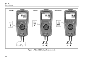
AC and DC Voltage Measurements 18 279 FC Users Manual VVooltlstsAACC VVooltlstsDDCC MMiilllilvivooltlstsDDCC iFlex iFlex iFlex Figure 4.
AC and DC Voltage Measurements 18 279 FC Users Manual VVooltlstsAACC VVooltlstsDDCC MMiilllilvivooltlstsDDCC iFlex iFlex iFlex Figure 4.

User Manual
Page 29
.... Low-Pass Filter AC measurements use an ac low-pass filter (). Low-Pass Filter True-rms Thermal Multimeter Basic Measurements x1 HzAC x2 V/HzAC iFlex Figure 6. See Figure 6. The low-pass filter can be invalid. Volt/Hertz Ratio 19 When the Multimeter is set to the Volts/Hz function, the...
.... Low-Pass Filter AC measurements use an ac low-pass filter (). Low-Pass Filter True-rms Thermal Multimeter Basic Measurements x1 HzAC x2 V/HzAC iFlex Figure 6. See Figure 6. The low-pass filter can be invalid. Volt/Hertz Ratio 19 When the Multimeter is set to the Volts/Hz function, the...
User Manual
Page 30
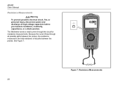
Because the current flows through the circuit for resistance measurements. See Figure 7. The Multimeter sends a small current through iFlex all possible paths between the probes. Figure 7. Resistance Measurements 20 279 FC Users Manual Resistance Measurements XW Warning To prevent possible electrical shock, fire, or personal injury, disconnect power and discharge all paths between the probes, the resistance measured is the total resistance of all high-voltage capacitors before you measure resistance, continuity, capacitance, or a diode junction.
Because the current flows through the circuit for resistance measurements. See Figure 7. The Multimeter sends a small current through iFlex all possible paths between the probes. Figure 7. Resistance Measurements 20 279 FC Users Manual Resistance Measurements XW Warning To prevent possible electrical shock, fire, or personal injury, disconnect power and discharge all paths between the probes, the resistance measured is the total resistance of all high-voltage capacitors before you measure resistance, continuity, capacitance, or a diode junction.
User Manual
Page 31
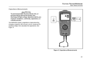
True-rms Thermal Multimeter Basic Measurements iFlex Figure 8. Capacitance Measurements XW Warning To prevent possible electrical shock, fire, or personal injury, disconnect power and discharge all high-voltage capacitors before you measure resistance, continuity, capacitance, or a diode junction. Capacitance Measurements 21 The Multimeter makes a capacitance measurement by charging a capacitor with a known current, measures the resulting voltage, then calculates the capacitance. See Figure 8.
True-rms Thermal Multimeter Basic Measurements iFlex Figure 8. Capacitance Measurements XW Warning To prevent possible electrical shock, fire, or personal injury, disconnect power and discharge all high-voltage capacitors before you measure resistance, continuity, capacitance, or a diode junction. Capacitance Measurements 21 The Multimeter makes a capacitance measurement by charging a capacitor with a known current, measures the resulting voltage, then calculates the capacitance. See Figure 8.
User Manual
Page 32
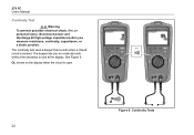
iFlex iFlex OL shows on the display when the circuit is sensed. The continuity test uses a beeper that sounds when a closed circuit is open. See Figure 9. Figure 9. The beeper lets you measure resistance, continuity, capacitance, or a diode junction. 279 FC Users Manual Continuity Test XW Warning To prevent possible electrical shock, fire, or personal injury, disconnect power and discharge all high-voltage capacitors before you do continuity tests without the necessity to look at the display. Continuity Tests 22
iFlex iFlex OL shows on the display when the circuit is sensed. The continuity test uses a beeper that sounds when a closed circuit is open. See Figure 9. Figure 9. The beeper lets you measure resistance, continuity, capacitance, or a diode junction. 279 FC Users Manual Continuity Test XW Warning To prevent possible electrical shock, fire, or personal injury, disconnect power and discharge all high-voltage capacitors before you do continuity tests without the necessity to look at the display. Continuity Tests 22

User Manual
Page 33
... Flexible Current Probe if the inner contrasting insulation color is not possible, an additional measurement error of ±2 % of the Flexible Current Probe. Connect the iFlex Current Probe to other currentcarrying conductors if possible. 4. Observe the ac current value. 23 AC Current Measurements XW Warning To prevent possible electrical shock, fire...
... Flexible Current Probe if the inner contrasting insulation color is not possible, an additional measurement error of ±2 % of the Flexible Current Probe. Connect the iFlex Current Probe to other currentcarrying conductors if possible. 4. Observe the ac current value. 23 AC Current Measurements XW Warning To prevent possible electrical shock, fire...
User Manual
Page 36
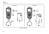
279 FC Users Manual GooooddDDioidoede Forward Bias GGoooodd DDiiooddee RReveevresresBeiaBsias BBaadd DDiiooddee iFlex BaaddDDioidoede 1 BBEEEEPP OPOEPNEN Figure 11. Diode Test 26 anadndShSohrteodrted
279 FC Users Manual GooooddDDioidoede Forward Bias GGoooodd DDiiooddee RReveevresresBeiaBsias BBaadd DDiiooddee iFlex BaaddDDioidoede 1 BBEEEEPP OPOEPNEN Figure 11. Diode Test 26 anadndShSohrteodrted

User Manual
Page 45
True-rms Thermal Multimeter Parts and Accessories Item Table 6. iFlex Current Probe Fluke Part or Model Number 4693466 TL175 AC175 4694103 4717467 TPAK80-4-8001 TPAK80-2003 1671807 3087338 BP500 BC500 i2500-10 i2500-18 35 Accessories and Replacement ... Information 9-inch Hanger Strap Hanging Clip USB A to USB mini-B Cable Soft Carry Case 7.4 V 3000 mAh Rechargeable Lithium-Ion Battery 15 V dc Charger 10 in . iFlex Current Probe 18 in .
True-rms Thermal Multimeter Parts and Accessories Item Table 6. iFlex Current Probe Fluke Part or Model Number 4693466 TL175 AC175 4694103 4717467 TPAK80-4-8001 TPAK80-2003 1671807 3087338 BP500 BC500 i2500-10 i2500-18 35 Accessories and Replacement ... Information 9-inch Hanger Strap Hanging Clip USB A to USB mini-B Cable Soft Carry Case 7.4 V 3000 mAh Rechargeable Lithium-Ion Battery 15 V dc Charger 10 in . iFlex Current Probe 18 in .

User Manual
Page 51
True-rms Thermal Multimeter Detailed Specifications AC Current with iFlex i2500 Range 1.0 A ac to 2500 A ac Resolution 1.0 A to 999.9 A 0.1 A 1000 A to 2500 A 1 A Measurement 3 % ±5 digits (45 Hz to 500 Hz) Crest Factor (50 Hz/60 Hz) add 2 % for C.F. >2 1100 A 3.0 1400 A 2.5 2500 A 1.42 Frequency Measurement Range 99.99 Hz 999.9 Hz [1] Frequency is specified up to 500 Hz • 2 Amps in V ac and V dc to 500 Hz. Minimum sensitivity: • 5 % of range in A ac 0.01 Hz 0.1 Hz Resolution 0.1 % + 1 0.1 % + 1 Measurement [1] 41
True-rms Thermal Multimeter Detailed Specifications AC Current with iFlex i2500 Range 1.0 A ac to 2500 A ac Resolution 1.0 A to 999.9 A 0.1 A 1000 A to 2500 A 1 A Measurement 3 % ±5 digits (45 Hz to 500 Hz) Crest Factor (50 Hz/60 Hz) add 2 % for C.F. >2 1100 A 3.0 1400 A 2.5 2500 A 1.42 Frequency Measurement Range 99.99 Hz 999.9 Hz [1] Frequency is specified up to 500 Hz • 2 Amps in V ac and V dc to 500 Hz. Minimum sensitivity: • 5 % of range in A ac 0.01 Hz 0.1 Hz Resolution 0.1 % + 1 0.1 % + 1 Measurement [1] 41

Calibration Guide
Page 3
Table of Contents Title Page Introduction 1 Contact Fluke 1 Safety Information 2 Symbols 3 Hazardous Voltage 3 Test Lead Alert 3 Display OL 3 Specifications 4 Detailed Specifications 5 AC Voltage Measurements 5 DC Voltage, Continuity, Resistance, Diode Test, and Capacitance Measurements 5 AC Current with iFlex i2500 5 Frequency Measurement 6 Input Characteristics 6 MIN MAX Recording 6 Infrared Camera 6 Required Equipment 7 Performance Tests 7 Display Test...
Table of Contents Title Page Introduction 1 Contact Fluke 1 Safety Information 2 Symbols 3 Hazardous Voltage 3 Test Lead Alert 3 Display OL 3 Specifications 4 Detailed Specifications 5 AC Voltage Measurements 5 DC Voltage, Continuity, Resistance, Diode Test, and Capacitance Measurements 5 AC Current with iFlex i2500 5 Frequency Measurement 6 Input Characteristics 6 MIN MAX Recording 6 Infrared Camera 6 Required Equipment 7 Performance Tests 7 Display Test...

Calibration Guide
Page 9
Accuracy specifications take the form of ±([% of Reading] + [Number of reading + 2 % full scale) typical, for 1 year after calibration, at operating temperatures of 18 °C to 28 °C, with relative humidity at 2 1100 A 3.0 1400 A 2.5 2500 A 1.42 5 True-rms Thermal Multimeter Detailed Specifications Detailed Specifications For all specifications: Accuracy is specified for crest factor up to 3. [4] Do not exceed 107 V-Hz. [5] Full-time low-pass filter. 200 Hz to 500 Hz ±(15.0 % + 3)[5] DC Voltage, Continuity, Resistance, Diode Test, and Capacitance Measurements ...
Accuracy specifications take the form of ±([% of Reading] + [Number of reading + 2 % full scale) typical, for 1 year after calibration, at operating temperatures of 18 °C to 28 °C, with relative humidity at 2 1100 A 3.0 1400 A 2.5 2500 A 1.42 5 True-rms Thermal Multimeter Detailed Specifications Detailed Specifications For all specifications: Accuracy is specified for crest factor up to 3. [4] Do not exceed 107 V-Hz. [5] Full-time low-pass filter. 200 Hz to 500 Hz ±(15.0 % + 3)[5] DC Voltage, Continuity, Resistance, Diode Test, and Capacitance Measurements ...
Calibration Guide
Page 12
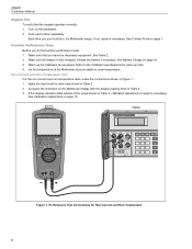
... the range shown in Figure 1. 1. Make sure that the keypad operates correctly: 1. Charge the battery if necessary. If not, repair is fully charged. See Contact Fluke on page 15. 279 FC 5522A iFlex Figure 1. Compare the indication on the Multimeter display with the display reading limits in Table 3. 2.
... the range shown in Figure 1. 1. Make sure that the keypad operates correctly: 1. Charge the battery if necessary. If not, repair is fully charged. See Contact Fluke on page 15. 279 FC 5522A iFlex Figure 1. Compare the indication on the Multimeter display with the display reading limits in Table 3. 2.
Calibration Guide
Page 13
... Depending on the target, the display temperature accuracy is free of that the target is invalid. Ice or moisture on page 15. 279 FC iFlex 5522A Figure 2. To avoid ice buildup, the 4180 has a cover with the display reading limits in Table 3. 2. Purge Procedure The cover allows... the target to assure that environment. If any set-point below Dew Point) WCaution For IR calibration with the Fluke 4180 IR Precision Calibrator, it is a slight amount) is on the ambient humidity of the range shown in Figure 2. 1. Connect a 6 mm (0....
... Depending on the target, the display temperature accuracy is free of that the target is invalid. Ice or moisture on page 15. 279 FC iFlex 5522A Figure 2. To avoid ice buildup, the 4180 has a cover with the display reading limits in Table 3. 2. Purge Procedure The cover allows... the target to assure that environment. If any set-point below Dew Point) WCaution For IR calibration with the Fluke 4180 IR Precision Calibrator, it is a slight amount) is on the ambient humidity of the range shown in Figure 2. 1. Connect a 6 mm (0....

Calibration Guide
Page 15
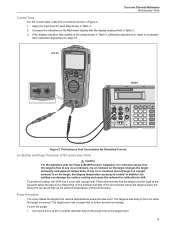
IR Camera Performance Test Configuration 11 Fluke 4180/4181 Fluke 279 FC iFlex True-rms Thermal Multimeter Performance Tests 20 in 51 cm Figure 3.
IR Camera Performance Test Configuration 11 Fluke 4180/4181 Fluke 279 FC iFlex True-rms Thermal Multimeter Performance Tests 20 in 51 cm Figure 3.
