
English Manual.
Page 6
... Memory 10 Install an Expansion Card 12 Install other Internal Connectors 13 Jumpers 17 Chapter 3 BIOS Setup Enter BIOS Setup 20 Main Menu 20 System Information 22 Green System Mode 24 Advanced BIOS Features 27 Fox Central Control Unit 29 Advanced Chipset Features 35 Integrated Peripherals 38... BIOS Security Features 42 Load Optimal Defaults 43 Save Changes and Exit 43 Discard Changes and Exit 43 ...
... Memory 10 Install an Expansion Card 12 Install other Internal Connectors 13 Jumpers 17 Chapter 3 BIOS Setup Enter BIOS Setup 20 Main Menu 20 System Information 22 Green System Mode 24 Advanced BIOS Features 27 Fox Central Control Unit 29 Advanced Chipset Features 35 Integrated Peripherals 38... BIOS Security Features 42 Load Optimal Defaults 43 Save Changes and Exit 43 Discard Changes and Exit 43 ...
English Manual.
Page 7
... Power Plan 71 Turbo Function 72 Chapter 5 RAID Configuration RAID Configuration Introduction 75 Option ROM Utility 77 Create a RAID Driver Diskette 79 RAID Enable in BIOS 81 Select a RAID Array for Use 81 Install a New Windows XP 96 Setting Up a Non-Bootable RAID Array 100 Technical Support : Website : http://www.foxconnchannel...
... Power Plan 71 Turbo Function 72 Chapter 5 RAID Configuration RAID Configuration Introduction 75 Option ROM Utility 77 Create a RAID Driver Diskette 79 RAID Enable in BIOS 81 Select a RAID Array for Use 81 Install a New Windows XP 96 Setting Up a Non-Bootable RAID Array 100 Technical Support : Website : http://www.foxconnchannel...

English Manual.
Page 17
... same capacity, brand, speed, and chips be installed in your system. Dual Channel - - CAUTION 10 Dual Channel DS/SS DS/SS - It is installed, the BIOS will automatically check the memory in only one direction. DS/SS DS/SS ! Dual Channel Memory Configuration This motherboard provides four DDR3 memory sockets and...
... same capacity, brand, speed, and chips be installed in your system. Dual Channel - - CAUTION 10 Dual Channel DS/SS DS/SS - It is installed, the BIOS will automatically check the memory in only one direction. DS/SS DS/SS ! Dual Channel Memory Configuration This motherboard provides four DDR3 memory sockets and...
English Manual.
Page 19
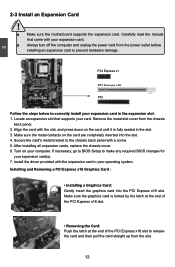
If necessary, go to BIOS Setup to correctly install your operating system. Locate an expansion slot that came with a screw. 5. Remove the metal slot cover from the slot. 12 Make ... with the slot, and press down on your expansion card(s). 7. PCI Express x1 PCI Express x16 PCI Follow the steps below to make any required BIOS changes for your computer.
If necessary, go to BIOS Setup to correctly install your operating system. Locate an expansion slot that came with a screw. 5. Remove the metal slot cover from the slot. 12 Make ... with the slot, and press down on your expansion card(s). 7. PCI Express x1 PCI Express x16 PCI Follow the steps below to make any required BIOS changes for your computer.

English Manual.
Page 21
... auxiliary power for better graphics performance and future upgrade usage. User must purchase another end with 10-pin female connector to connect speaker of the BIOS Setup. If you need to align the ATX power connector according to connect with the external RS232 device and another RS232 cable with a 9-pin D-sub...
... auxiliary power for better graphics performance and future upgrade usage. User must purchase another end with 10-pin female connector to connect speaker of the BIOS Setup. If you need to align the ATX power connector according to connect with the external RS232 device and another RS232 cable with a 9-pin D-sub...

English Manual.
Page 24
...the jumper settings on . 17 The following content carefully prior to short them . Remove jumper cap from the power outlet. 2. Go to BIOS Setup to clear CMOS data are : 1. 2 2-5 Jumpers For some features needed, users can prevent hazardous ESD (Electrical Static Discharge) problem.... ■ Disconnect the power cable before adjusting the jumper settings. ■ Do not clear the CMOS while the system is simply labeled as BIOS data, date, time information, hardware password...etc.). This will clear CMOS data. 3. Description of the jumper settings. However, in the power ...
...the jumper settings on . 17 The following content carefully prior to short them . Remove jumper cap from the power outlet. 2. Go to BIOS Setup to clear CMOS data are : 1. 2 2-5 Jumpers For some features needed, users can prevent hazardous ESD (Electrical Static Discharge) problem.... ■ Disconnect the power cable before adjusting the jumper settings. ■ Do not clear the CMOS while the system is simply labeled as BIOS data, date, time information, hardware password...etc.). This will clear CMOS data. 3. Description of the jumper settings. However, in the power ...

English Manual.
Page 26
... Optimal Defaults ■ Save Changes and Exit ■ Discard Changes and Exit Since BIOS could be updated some other times, the BIOS information described in this manual will remain consistent with the newly released BIOS at any given time in the future. This chapter includes the following cases occur: ... provided. Please visit our website for updated manual if it is for reference only. You have to change system settings through the BIOS Setup menus. This chapter tells how to change the default CMOS settings. Detailed descriptions of this manual is available. An error message...
... Optimal Defaults ■ Save Changes and Exit ■ Discard Changes and Exit Since BIOS could be updated some other times, the BIOS information described in this manual will remain consistent with the newly released BIOS at any given time in the future. This chapter includes the following cases occur: ... provided. Please visit our website for updated manual if it is for reference only. You have to change system settings through the BIOS Setup menus. This chapter tells how to change the default CMOS settings. Detailed descriptions of this manual is available. An error message...

English Manual.
Page 27
...(C) 1985-2008, American Megatrends, Inc. ► System Information ► Integrated Peripherals ► Green System Mode ► BIOS Security Features ► Advanced BIOS Features Load Optimal Defaults ► Fox Central Control Unit Save Changes and Exit ► Advanced Chipset Features Discard Changes and ...select from the change you can press key to the submenu. There are boot up through this menu. ► Advanced BIOS Features The advanced system features can be set up through this menu. ► Advanced Chipset Features The values for any ...
...(C) 1985-2008, American Megatrends, Inc. ► System Information ► Integrated Peripherals ► Green System Mode ► BIOS Security Features ► Advanced BIOS Features Load Optimal Defaults ► Fox Central Control Unit Save Changes and Exit ► Advanced Chipset Features Discard Changes and ...select from the change you can press key to the submenu. There are boot up through this menu. ► Advanced BIOS Features The advanced system features can be set up through this menu. ► Advanced Chipset Features The values for any ...

English Manual.
Page 28
... All onboard peripherals can be set a password, the system will ask you to key in some ways (such as Serial I /O cards installed. etc. ► BIOS Security Features The Supervisor/User password can be set to Setup. ► Load Optimal Defaults The optimal performance settings can be loaded through this menu...; Save Changes and Exit Save setting values to find out the best setting for your computer. It means, if your system loading is to adjust BIOS setting one by one, trial and error, to CMOS and exit. ► Discard Changes and Exit Do not change anything and exit the setup....
... All onboard peripherals can be set a password, the system will ask you to key in some ways (such as Serial I /O cards installed. etc. ► BIOS Security Features The Supervisor/User password can be set to Setup. ► Load Optimal Defaults The optimal performance settings can be loaded through this menu...; Save Changes and Exit Save setting values to find out the best setting for your computer. It means, if your system loading is to adjust BIOS setting one by one, trial and error, to CMOS and exit. ► Discard Changes and Exit Do not change anything and exit the setup....

English Manual.
Page 29
... E-SATA# When OnChip SATA Type is the upper SATA port of SATA devices. SATA4# is set to [Native IDE], while entering setup, BIOS automatically detects the presence of SATA3_SATA4. SATA1# is the lower SATA port of SATA5_ESATA. ► Floppy A This option allows you to configure ...[Not Detected] Floppy A Halt On Keyboard Mouse Floppy [1.44 MB 31/2"] [All Errors, But ...] [Disabled] [Disabled] [Disabled] Model Name BIOS ID : A7DA 3 series : 8C2F1P01 Move Enter:Select +/-/:Value F10:Save ESC:Exit F1:General Help F9:Optimized Defaults 3 ► Date (mm:dd:yy) format...
... E-SATA# When OnChip SATA Type is the upper SATA port of SATA devices. SATA4# is set to [Native IDE], while entering setup, BIOS automatically detects the presence of SATA3_SATA4. SATA1# is the lower SATA port of SATA5_ESATA. ► Floppy A This option allows you to configure ...[Not Detected] Floppy A Halt On Keyboard Mouse Floppy [1.44 MB 31/2"] [All Errors, But ...] [Disabled] [Disabled] [Disabled] Model Name BIOS ID : A7DA 3 series : 8C2F1P01 Move Enter:Select +/-/:Value F10:Save ESC:Exit F1:General Help F9:Optimized Defaults 3 ► Date (mm:dd:yy) format...

English Manual.
Page 30
... stop for a floppy error if you enabled this item. ► Model Name Model name of this information and discuss with the field service people if a BIOS upgrade is detected during powering up. [All Errors] : All errors can result in system halt. [All Errors But...] : All errors but keyboard or mouse or...; CPU Name It displays the current CPU name. ► Memory This item displays the current memory size. The halt condition can check this product. ► BIOS ID / BIOS Version It displays the current...
... stop for a floppy error if you enabled this item. ► Model Name Model name of this information and discuss with the field service people if a BIOS upgrade is detected during powering up. [All Errors] : All errors can result in system halt. [All Errors But...] : All errors but keyboard or mouse or...; CPU Name It displays the current CPU name. ► Memory This item displays the current memory size. The halt condition can check this product. ► BIOS ID / BIOS Version It displays the current...
English Manual.
Page 31
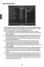
... Disk) S5 - CPU, cache, and chip set ) and hardware maintains all system context is lost (the OS is responsible for initial boot operations within the BIOS to distinguish whether or not the boot is maintained. (also called Suspend to a minimum, it wakes. 3 Green System Mode CMOS Setup Utility - The S1 sleeping...
... Disk) S5 - CPU, cache, and chip set ) and hardware maintains all system context is lost (the OS is responsible for initial boot operations within the BIOS to distinguish whether or not the boot is maintained. (also called Suspend to a minimum, it wakes. 3 Green System Mode CMOS Setup Utility - The S1 sleeping...

English Manual.
Page 34
... may be allocated to each PCI device can hold the bus before they can retain control of PCI cycle for detecting ATA/ATAPI devices. Advanced BIOS Features IDE Detect Time Out MPS Revision PCI Latency Timer Quiet Boot Quick Boot Bootup Num-Lock Floppy Drive Seek ► Boot Device Priority ►..., 160, 192, 224, 248. Low values for a secondary PCI bus without requiring a PCI bridge. If your operating system comes with two or more processors. Advanced BIOS Features CMOS Setup Utility - Copyright (C) 1985-2006, American Megatrends, Inc.
... may be allocated to each PCI device can hold the bus before they can retain control of PCI cycle for detecting ATA/ATAPI devices. Advanced BIOS Features IDE Detect Time Out MPS Revision PCI Latency Timer Quiet Boot Quick Boot Bootup Num-Lock Floppy Drive Seek ► Boot Device Priority ►..., 160, 192, 224, 248. Low values for a secondary PCI bus without requiring a PCI bridge. If your operating system comes with two or more processors. Advanced BIOS Features CMOS Setup Utility - Copyright (C) 1985-2006, American Megatrends, Inc.

English Manual.
Page 35
.... ► CD/DVD Drives This option is started. The available settings are: On (default) and Off. ► Floppy Drive Seek This item controls whether the BIOS will shorten the time needed to boot the system. ► Bootup Num-Lock This item defines if the keyboard Num Lock key is active when... booting up. 3 [Disabled] : Displays the normal POST messages. [Enabled] : Displays OEM customer logo instead of POST messages. ► Quick Boot While Enabled, this option allows BIOS to skip certain tests while booting, this will be checking for boot devices.
.... ► CD/DVD Drives This option is started. The available settings are: On (default) and Off. ► Floppy Drive Seek This item controls whether the BIOS will shorten the time needed to boot the system. ► Bootup Num-Lock This item defines if the keyboard Num Lock key is active when... booting up. 3 [Disabled] : Displays the normal POST messages. [Enabled] : Displays OEM customer logo instead of POST messages. ► Quick Boot While Enabled, this option allows BIOS to skip certain tests while booting, this will be checking for boot devices.

English Manual.
Page 36
...Press Enter] Enabled Move Enter:Select +/-/:Value F10:Save ESC:Exit F1:General Help F9:Optimized Defaults ► Super BIOS Protect To protect the system BIOS from being affected by viruses, e.g. When enabled, the system will turn off clock of the empty PCI slot to ...reduce EMI (Electromagnetic Interference). ► Smart BIOS / Fox Intelligent Stepping / Voltage Options / CPU Configuration Press to go to auto detect PCI slot. Copyright (C) 1985-2006, American Megatrends, Inc. Super BIOS Protect function protects your BIOS from virus attack, there is used to its submenu...
...Press Enter] Enabled Move Enter:Select +/-/:Value F10:Save ESC:Exit F1:General Help F9:Optimized Defaults ► Super BIOS Protect To protect the system BIOS from being affected by viruses, e.g. When enabled, the system will turn off clock of the empty PCI slot to ...reduce EMI (Electromagnetic Interference). ► Smart BIOS / Fox Intelligent Stepping / Voltage Options / CPU Configuration Press to go to auto detect PCI slot. Copyright (C) 1985-2006, American Megatrends, Inc. Super BIOS Protect function protects your BIOS from virus attack, there is used to its submenu...

English Manual.
Page 37
..., Inc. Off), one long On (1sec.), continuously. This also prevents user without password trying to get into your motherboard to enter smart boot menu. Smart BIOS Smart Power LED [Enabled] Help Item Smart Boot Menu Current CPU Speed [Enabled] : 2800MHz Options Current NB Speed : 2000MHz Current FSB/HTT Speed : 200MHz Current... blinking On (1sec.), Off (1sec.) Continue blinking On (2sec.), Off (2sec.) Quick blinking twice (1/3sec. You can always leave this state enabled. On, 1/3sec. Smart BIOS CMOS Setup Utility -
..., Inc. Off), one long On (1sec.), continuously. This also prevents user without password trying to get into your motherboard to enter smart boot menu. Smart BIOS Smart Power LED [Enabled] Help Item Smart Boot Menu Current CPU Speed [Enabled] : 2800MHz Options Current NB Speed : 2000MHz Current FSB/HTT Speed : 200MHz Current... blinking On (1sec.), Off (1sec.) Continue blinking On (2sec.), Off (2sec.) Quick blinking twice (1/3sec. You can always leave this state enabled. On, 1/3sec. Smart BIOS CMOS Setup Utility -

English Manual.
Page 39
... HT Speed setting. ► NCHT Incoming Link Width / NCHT Outcoming Link Width The coherency refers to achieve the function, including AMD OverDrive tool and compatible BIOS. The CPUNB HT Speed option controls the physical speed of the link is highly recommended to set to 13x. Setting values are coherent HT links...
... HT Speed setting. ► NCHT Incoming Link Width / NCHT Outcoming Link Width The coherency refers to achieve the function, including AMD OverDrive tool and compatible BIOS. The CPUNB HT Speed option controls the physical speed of the link is highly recommended to set to 13x. Setting values are coherent HT links...
English Manual.
Page 43
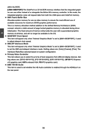
... [UMA+SIDEPORT], it used to adjust sideport clock speed. ► UMA-SP Interleave Mode This item will request data from different display devices. 3 within the BIOS. [UMA+SIDEPORT]-The SidePort is a 32-bit DDR memory interface that the integrated graphics can use of available resources for use as video memory to...
... [UMA+SIDEPORT], it used to adjust sideport clock speed. ► UMA-SP Interleave Mode This item will request data from different display devices. 3 within the BIOS. [UMA+SIDEPORT]-The SidePort is a 32-bit DDR memory interface that the integrated graphics can use of available resources for use as video memory to...
English Manual.
Page 44
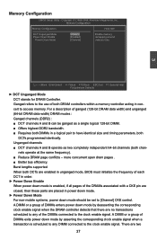
... a description of both channels operate at the same frequency). ■ Reduce DRAM page conflicts - Burst lengths supported When both DCTs are enabled in unganged mode, BIOS must initialize the frequency of each DCT in order. ► Power Down Enable When power down mode is enabled, if all pages of the DRAMs...
... a description of both channels operate at the same frequency). ■ Reduce DRAM page conflicts - Burst lengths supported When both DCTs are enabled in unganged mode, BIOS must initialize the frequency of each DCT in order. ► Power Down Enable When power down mode is enabled, if all pages of the DRAMs...

English Manual.
Page 48
... OnBoard Floppy Controller Serial Port1 Address Serial Port2 Address Serial Port2 Mode Serial Port2 Duplex Mode [Enabled] [3F8/IRQ4] [2F8/IRQ3] [IrDA] [Half Duplex] Allows BIOS to set the transfer mode of the onboard serial port 2. 3 SuperIO Configuration CMOS Setup Utility - Move Enter:Select +/-/:Value F10:Save ESC:Exit F1:General...
... OnBoard Floppy Controller Serial Port1 Address Serial Port2 Address Serial Port2 Mode Serial Port2 Duplex Mode [Enabled] [3F8/IRQ4] [2F8/IRQ3] [IrDA] [Half Duplex] Allows BIOS to set the transfer mode of the onboard serial port 2. 3 SuperIO Configuration CMOS Setup Utility - Move Enter:Select +/-/:Value F10:Save ESC:Exit F1:General...


