
English Manual.
Page 1
A9DA Series Motherboard User's Manual
A9DA Series Motherboard User's Manual

English Manual.
Page 2
...of these changes. By ensuring this product is the intellectual property of Foxconn, Inc. All trade names are the property of their respective owners. WEEE: The use motherboard better, and tells you purchased this product. Although the information in... this product may be treated as household waste. CAUTION Statement: This manual is disposed of correctly, you will help you to use of this symbol indicates that can help prevent potential negative consequences for A9DA Series motherboard...
...of these changes. By ensuring this product is the intellectual property of Foxconn, Inc. All trade names are the property of their respective owners. WEEE: The use motherboard better, and tells you purchased this product. Although the information in... this product may be treated as household waste. CAUTION Statement: This manual is disposed of correctly, you will help you to use of this symbol indicates that can help prevent potential negative consequences for A9DA Series motherboard...

English Manual.
Page 3
... information technology equipment ■ EN 61000-3-2/:2000 Electromagnetic compatibility (EMC) Part 3: Limits Section 2: Limits for harmonic current emissions (equipment input current declares that the product Motherboard A9DA-S/A9DA is in conformity with (reference to the specification under which conformity is declared in accordance with 89/336 EEC-EMC Directive) ■ EN 55022:1998...
... information technology equipment ■ EN 61000-3-2/:2000 Electromagnetic compatibility (EMC) Part 3: Limits Section 2: Limits for harmonic current emissions (equipment input current declares that the product Motherboard A9DA-S/A9DA is in conformity with (reference to the specification under which conformity is declared in accordance with 89/336 EEC-EMC Directive) ■ EN 55022:1998...

English Manual.
Page 4
... Rules. Signature : Date : 2010 Lambert Rd. Supplementary Information: This device complies with FCC standards. Declaration of Product: Manufacturer: Address: FCC Class B Subassembly Motherboard HON HAI PRECISION INDUSTRY COMPANY LTD 66 , CHUNG SHAN RD., TU-CHENG INDUSTRIAL DISTRICT, TAIPEI HSIEN, TAIWAN, R.O.C. Tested to the following two conditions : (1)...CA 92835 714-738-8868 714-738-8838 Equipment Classification: Type of conformity Trade Name: Model Name: Responsible Party: Address: Telephone: Facsimile: FOXCONN A9DA-S/A9DA PCE Industry Inc. 458 E.
... Rules. Signature : Date : 2010 Lambert Rd. Supplementary Information: This device complies with FCC standards. Declaration of Product: Manufacturer: Address: FCC Class B Subassembly Motherboard HON HAI PRECISION INDUSTRY COMPANY LTD 66 , CHUNG SHAN RD., TU-CHENG INDUSTRIAL DISTRICT, TAIPEI HSIEN, TAIWAN, R.O.C. Tested to the following two conditions : (1)...CA 92835 714-738-8868 714-738-8838 Equipment Classification: Type of conformity Trade Name: Model Name: Responsible Party: Address: Telephone: Facsimile: FOXCONN A9DA-S/A9DA PCE Industry Inc. 458 E.

English Manual.
Page 5
.... Also, make sure the power supply AC input voltage setting has been configured to the local standard. ■ To prevent damage to the motherboard, do not allow screws to unplug the AC power cord from the power supply outlet. Incorrect con- Please carefully read the following procedures to ...computer : ■ It is the sudden and momentary electric current that your system can operate normally when your system. ! Never turn on the motherboard or within the computer casing. ■ If you are no leftover screws or metal components placed on the computer if the CPU fan is not...
.... Also, make sure the power supply AC input voltage setting has been configured to the local standard. ■ To prevent damage to the motherboard, do not allow screws to unplug the AC power cord from the power supply outlet. Incorrect con- Please carefully read the following procedures to ...computer : ■ It is the sudden and momentary electric current that your system can operate normally when your system. ! Never turn on the motherboard or within the computer casing. ■ If you are no leftover screws or metal components placed on the computer if the CPU fan is not...

English Manual.
Page 8
With advanced overclocking capability and a range of connectivity features for today multi-media computing requirements, A9DA-S/ A9DA enables you need for buying Foxconn A9DA Series motherboard. Foxconn products are engineered to maximize computing power, providing only what you to unleash more power from your computer. Thank you for break-through performance. This chapter includes the following information: ■ Product Specifications ■ Layout ■ Back Panel Connectors
With advanced overclocking capability and a range of connectivity features for today multi-media computing requirements, A9DA-S/ A9DA enables you need for buying Foxconn A9DA Series motherboard. Foxconn products are engineered to maximize computing power, providing only what you to unleash more power from your computer. Thank you for break-through performance. This chapter includes the following information: ■ Product Specifications ■ Layout ■ Back Panel Connectors

English Manual.
Page 11
CD_IN Connector 7. Front Audio Connector 8. 1394a Connector (only for A9DA-S) 13. Power on Button (only for A9DA-S) 9. Clear CMOS Button 18. 24-pin ATX Power Connector 19. NB_FAN Header 3. Front Panel Connector 14. South Bridge: AMD SB850 21... CPU Socket 22. Front USB Connectors 11. North Bridge: RS880D 23. 8-pin ATX 12V Power Connector Note : The above motherboard layout is for reference only, please refer to the physical motherboard for A9DA-S) 12. CPU_FAN Header 2. Speaker Connector 16. DDR3 DIMM Slots 20. COM1 Connector 15. PCI Express x16 Slots 4. 1 1-2...
CD_IN Connector 7. Front Audio Connector 8. 1394a Connector (only for A9DA-S) 13. Power on Button (only for A9DA-S) 9. Clear CMOS Button 18. 24-pin ATX Power Connector 19. NB_FAN Header 3. Front Panel Connector 14. South Bridge: AMD SB850 21... CPU Socket 22. Front USB Connectors 11. North Bridge: RS880D 23. 8-pin ATX 12V Power Connector Note : The above motherboard layout is for reference only, please refer to the physical motherboard for A9DA-S) 12. CPU_FAN Header 2. Speaker Connector 16. DDR3 DIMM Slots 20. COM1 Connector 15. PCI Express x16 Slots 4. 1 1-2...

English Manual.
Page 14
... ■ Install an Expansion Card ■ Install other Internal Connectors ■ Jumpers Please visit the following website for more supporting information about your motherboard. Please refer to the motherboard layout prior to any installation and read the contents in this chapter carefully. CPU Support List: http://www.foxconnsupport.com/cpusupportlist.aspx Memory...
... ■ Install an Expansion Card ■ Install other Internal Connectors ■ Jumpers Please visit the following website for more supporting information about your motherboard. Please refer to the motherboard layout prior to any installation and read the contents in this chapter carefully. CPU Support List: http://www.foxconnsupport.com/cpusupportlist.aspx Memory...

English Manual.
Page 15
... of thermal grease on the surface of the CPU. ■ Do not turn on the computer if the CPU cooler is not recommended that the motherboard supports the CPU. ■ Always turn off the computer and unplug the power cord from the power supply before installing the CPU to your hardware...
... of thermal grease on the surface of the CPU. ■ Do not turn on the computer if the CPU cooler is not recommended that the motherboard supports the CPU. ■ Always turn off the computer and unplug the power cord from the power supply before installing the CPU to your hardware...

English Manual.
Page 16
Apply and spread an even thermal grease on the motherboard . ! CAUTION 3. Attach the 3-wire CPU cooler connector to the CPU fan header on the surface of the stand. Inadequately removing the CPU cooler may adhere ... down to the CPU. When CPU is properly seated, push the CPU socket lever back to correctly install the CPU cooler. (The following procedures use Foxconn cooler as the example.) 1.
Apply and spread an even thermal grease on the motherboard . ! CAUTION 3. Attach the 3-wire CPU cooler connector to the CPU fan header on the surface of the stand. Inadequately removing the CPU cooler may adhere ... down to the CPU. When CPU is properly seated, push the CPU socket lever back to correctly install the CPU cooler. (The following procedures use Foxconn cooler as the example.) 1.

English Manual.
Page 17
... installed, the BIOS will automatically check the memory in only one direction. Dual Channel Memory Configuration This motherboard provides four DDR3 memory sockets and supports Dual Channel Technology. When memory is recommended that the motherboard supports the memory. DS/SS - DS/SS - DS/SS DS/SS ! Four DDR3 memory sockets are divided...
... installed, the BIOS will automatically check the memory in only one direction. Dual Channel Memory Configuration This motherboard provides four DDR3 memory sockets and supports Dual Channel Technology. When memory is recommended that the motherboard supports the memory. DS/SS - DS/SS - DS/SS DS/SS ! Four DDR3 memory sockets are divided...

English Manual.
Page 18
.... Step 1: Spread the clips at both ends of memory module, it can only fit in the middle, so it has asymmetric pin counts on this motherboard. Before installing a memory module, make sure to turn off the computer and unplug the power cord from the power outlet to prevent damage to correctly...
.... Step 1: Spread the clips at both ends of memory module, it can only fit in the middle, so it has asymmetric pin counts on this motherboard. Before installing a memory module, make sure to turn off the computer and unplug the power cord from the power outlet to prevent damage to correctly...

English Manual.
Page 19
... card's metal bracket to the chassis back panel with the expansion card in the expansion slot. 1. 2 CAUTION 2-3 Install an Expansion Card ! ■ Make sure the motherboard supports the expansion card. Remove the metal slot cover from the slot. 12 Installing and Removing a PCI Express x16 Graphics Card : • Installing a Graphics Card...
... card's metal bracket to the chassis back panel with the expansion card in the expansion slot. 1. 2 CAUTION 2-3 Install an Expansion Card ! ■ Make sure the motherboard supports the expansion card. Remove the metal slot cover from the slot. 12 Installing and Removing a PCI Express x16 Graphics Card : • Installing a Graphics Card...

English Manual.
Page 20
...-pin ATX power connector : PWR1 PWR1 is secure. We recommend you using a 20-pin power supply, you are properly aligned with the connector on the motherboard. Make sure that the power supply cable and pins are using a 24-pin power supply. Pin # Definition Pin # Definition 1 3.3V 13 3.3V 2 3.3V 14 -12V.... 51 +12V GND 84 PWR2 Pin # 1 2 3 4 Definition GND GND GND GND Pin # 5 6 7 8 Definition +12V +12V +12V +12V 13 2 2-4 Install other Internal Connectors Power Connectors This motherboard uses an ATX power supply.
...-pin ATX power connector : PWR1 PWR1 is secure. We recommend you using a 20-pin power supply, you are properly aligned with the connector on the motherboard. Make sure that the power supply cable and pins are using a 24-pin power supply. Pin # Definition Pin # Definition 1 3.3V 13 3.3V 2 3.3V 14 -12V.... 51 +12V GND 84 PWR2 Pin # 1 2 3 4 Definition GND GND GND GND Pin # 5 6 7 8 Definition +12V +12V +12V +12V 13 2 2-4 Install other Internal Connectors Power Connectors This motherboard uses an ATX power supply.

English Manual.
Page 21
... connector is used to connect speaker of the BIOS Setup. 2 CAUTION ! SPKJ 1 EMPTY 2 NC 3 SPKJ 4 SPEAKER COM Connector : COM1 This motherboard supports one end to connect with the external RS232 device and another end with a 9-pin D-sub connector at one serial RS232 COM port for legacy...three main fan headers on the right. User must purchase another RS232 cable with 10-pin female connector to the picture on this motherboard. Connect a 4-pin power plug Fan Connectors : CPU_FAN, SYS_FAN, NB_FAN There are using a 4-pin power supply, you using an 8-pin ...
... connector is used to connect speaker of the BIOS Setup. 2 CAUTION ! SPKJ 1 EMPTY 2 NC 3 SPKJ 4 SPEAKER COM Connector : COM1 This motherboard supports one end to connect with the external RS232 device and another end with a 9-pin D-sub connector at one serial RS232 COM port for legacy...three main fan headers on the right. User must purchase another RS232 cable with 10-pin female connector to the picture on this motherboard. Connect a 4-pin power plug Fan Connectors : CPU_FAN, SYS_FAN, NB_FAN There are using a 4-pin power supply, you using an 8-pin ...

English Manual.
Page 22
... can use it to connect an ESATA hard disk to the upper SATA port of the chassis. Push this feature. 2 Front Panel Connector : FP1 This motherboard includes one connector for connecting the front panel switch and LED Indicators. When the system is directional with +/- When the system gets into sleep mode...
... can use it to connect an ESATA hard disk to the upper SATA port of the chassis. Push this feature. 2 Front Panel Connector : FP1 This motherboard includes one connector for connecting the front panel switch and LED Indicators. When the system is directional with +/- When the system gets into sleep mode...

English Manual.
Page 23
.... It provides the Front Audio output choice. 12 PORT1_L AUD_GND PORT1_R PRESENCE_J PORT2_R SENSE1_RETURN SENSE_SEND EMPTY PORT2_L SENSE2_RETURN 9 10 F_AUDIO 1394a Connector : F_1394 ( only for A9DA-S ) The 1394a expansion cable can be connected to the six USB ports on the rear panel, this product also provides four 10-pin USB headers... with the appropriate interface) or real panel of your chassis is a Sony standard audio connector, it can quickly expand another eight USB ports on its motherboard.
.... It provides the Front Audio output choice. 12 PORT1_L AUD_GND PORT1_R PRESENCE_J PORT2_R SENSE1_RETURN SENSE_SEND EMPTY PORT2_L SENSE2_RETURN 9 10 F_AUDIO 1394a Connector : F_1394 ( only for A9DA-S ) The 1394a expansion cable can be connected to the six USB ports on the rear panel, this product also provides four 10-pin USB headers... with the appropriate interface) or real panel of your chassis is a Sony standard audio connector, it can quickly expand another eight USB ports on its motherboard.

English Manual.
Page 24
..., users can change the jumper settings on the two pins to temporarily short them. Description of the jumper settings. However, in this motherboard to modify them. The shorting can also be identified by changing the jumper settings. The steps to configure new system as BIOS data.... Jumper 1 Diagram 1 1 Definition 1-2 2-3 Description Set Pin 1 and Pin 2 closed Set Pin 2 and Pin 3 closed Clear CMOS Jumper: CLR_CMOS The motherboard uses CMOS RAM to its original with pins 2-3 closed. 4. Return the setting to store the basic hardware information (such as described in the power cord...
..., users can change the jumper settings on the two pins to temporarily short them. Description of the jumper settings. However, in this motherboard to modify them. The shorting can also be identified by changing the jumper settings. The steps to configure new system as BIOS data.... Jumper 1 Diagram 1 1 Definition 1-2 2-3 Description Set Pin 1 and Pin 2 closed Set Pin 2 and Pin 3 closed Clear CMOS Jumper: CLR_CMOS The motherboard uses CMOS RAM to its original with pins 2-3 closed. 4. Return the setting to store the basic hardware information (such as described in the power cord...
English Manual.
Page 29
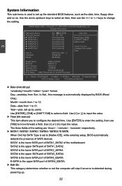
...] [Not Detected] Use [+] or [-] to 31. Date-date from 1 to [Not Detected] configure the system Date. [All Errors, But ...] [Disabled] [Enabled] Model Name :A9DA-S/A9DA BIOS ID :994F1D12 BIOS Version : 08.00.15 Memory Size : 2048MB MAC Address :00-00-00-00-00-00 CPU Name : AMD Phenom(tm) II...set up the standard BIOS features, such as the date, time, floppy drive and so on. SATA2 is the upper SATA port of the motherboard. SATA1 is the lower SATA port of SATA1_SATA2 of SATA1_SATA2. Year-year, set to change the setting. SATA4 is the upper SATA port of...
...] [Not Detected] Use [+] or [-] to 31. Date-date from 1 to [Not Detected] configure the system Date. [All Errors, But ...] [Disabled] [Enabled] Model Name :A9DA-S/A9DA BIOS ID :994F1D12 BIOS Version : 08.00.15 Memory Size : 2048MB MAC Address :00-00-00-00-00-00 CPU Name : AMD Phenom(tm) II...set up the standard BIOS features, such as the date, time, floppy drive and so on. SATA2 is the upper SATA port of the motherboard. SATA1 is the lower SATA port of SATA1_SATA2 of SATA1_SATA2. Year-year, set to change the setting. SATA4 is the upper SATA port of...

English Manual.
Page 31
...This feature controls how long each PCI device to each PCI device can hold the bus before they can get access to multiprocessor motherboards as it as 1.1 only if you should keep the setting as too much time may not agree with support for the PCI... 1.4 adds extended configuration tables for a longer time. MPS 1.1 was the original specification. Setting values are running an older operating system that the motherboard will have to wait longer before another takes over. Advanced BIOS Features CMOS Setup Utility - Copyright (C) 1985-2006, American Megatrends, Inc. Low ...
...This feature controls how long each PCI device to each PCI device can hold the bus before they can get access to multiprocessor motherboards as it as 1.1 only if you should keep the setting as too much time may not agree with support for the PCI... 1.4 adds extended configuration tables for a longer time. MPS 1.1 was the original specification. Setting values are running an older operating system that the motherboard will have to wait longer before another takes over. Advanced BIOS Features CMOS Setup Utility - Copyright (C) 1985-2006, American Megatrends, Inc. Low ...


