User manual
Page 6
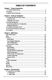
Install Utility 45 Install Driver 44 2. Table of Contents Chapter 1 Product Introduction 1-1 Product Specifications 2 1-2 Layout...4 1-3 Back Panel Connectors 5 Chapter 2 Hardware Installation 2-1 Install the CPU and CPU Cooler 8 Install the CPU 8 Install the CPU Cooler 10 2-2 Install the Memory 11 Dual Channel Memory ...
Install Utility 45 Install Driver 44 2. Table of Contents Chapter 1 Product Introduction 1-1 Product Specifications 2 1-2 Layout...4 1-3 Back Panel Connectors 5 Chapter 2 Hardware Installation 2-1 Install the CPU and CPU Cooler 8 Install the CPU 8 Install the CPU Cooler 10 2-2 Install the Memory 11 Dual Channel Memory ...

User manual
Page 8
Chapter 1 Product Introduction Thank you need for buying Foxconn B75MX Series motherboard. Foxconn products are engineered to maximize computing power, providing only what you for break-through performance. This chapter includes the following information: ■ Product Specifications ■ Layout ■ Back Panel Connectors
Chapter 1 Product Introduction Thank you need for buying Foxconn B75MX Series motherboard. Foxconn products are engineered to maximize computing power, providing only what you for break-through performance. This chapter includes the following information: ■ Product Specifications ■ Layout ■ Back Panel Connectors

User manual
Page 9
...) - 1 x SATA 3.0 connectors (6Gb/s data transfer rate) Realtek RTL8111DP-VC-CG Gigabit LAN controller (B75MX-S) Realtek RTL8111F-CG Gigabit LAN controller (B75MX/B75MX-D/B75MX-D PA) Support 10/100/1000Mbps Realtek ALC662-VD0-GR -High Definition Audio -2/4/5.1-channel -Support Jack-Sensing function ...Support up to 6 x USB 2.0 ports (2 rear panel ports, 2 onboard USB headers supporting 4 extra ports) Support up to 4 x USB 3.0 ports (2 rear panel...
...) - 1 x SATA 3.0 connectors (6Gb/s data transfer rate) Realtek RTL8111DP-VC-CG Gigabit LAN controller (B75MX-S) Realtek RTL8111F-CG Gigabit LAN controller (B75MX/B75MX-D/B75MX-D PA) Support 10/100/1000Mbps Realtek ALC662-VD0-GR -High Definition Audio -2/4/5.1-channel -Support Jack-Sensing function ...Support up to 6 x USB 2.0 ports (2 rear panel ports, 2 onboard USB headers supporting 4 extra ports) Support up to 4 x USB 3.0 ports (2 rear panel...

User manual
Page 10
... Software Operating System Form Factor 1 x Front panel header 1 x Front Audio header 1 x TPM/TCM header (only for B75MX/B75MX-S/B75MX-D) 1 x LPT header 1 x INTR header(only for B75MX/B75MX-S/B75MX-D) 1 x COM2 header 1 x Clear CMOS header 1 x ME header 1 x PS/2 Keyboard port 1 x PS/2 Mouse port 1 x RJ45 LAN port 1 x HDMI port (only for B75MX) 1 x DVI-D port (only for B75MX-S/B75MX-D/B75MX-D PA) 1 x VGA port 1 x COM port...
... Software Operating System Form Factor 1 x Front panel header 1 x Front Audio header 1 x TPM/TCM header (only for B75MX/B75MX-S/B75MX-D) 1 x LPT header 1 x INTR header(only for B75MX/B75MX-S/B75MX-D) 1 x COM2 header 1 x Clear CMOS header 1 x ME header 1 x PS/2 Keyboard port 1 x PS/2 Mouse port 1 x RJ45 LAN port 1 x HDMI port (only for B75MX) 1 x DVI-D port (only for B75MX-S/B75MX-D/B75MX-D PA) 1 x VGA port 1 x COM port...

User manual
Page 11
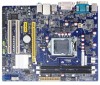
... Header 20. CPU_FAN Header 21. Front Audio Header 7. Front USB 2.0 Headers 11. PCI Express X16 Slot 3. LPT Header 8. INTR Header 5. PCI Express X1 Slot 4. Front Panel Header 14. DDR3 DIMM Slot 19. COM2 Header 2. PCI Slot 6. PRODUCT INTRODUCTION 1-2 Layout 6 543 2 1 7 22 8 9 10 21 20 11 19 12 18 13 14 15...
... Header 20. CPU_FAN Header 21. Front Audio Header 7. Front USB 2.0 Headers 11. PCI Express X16 Slot 3. LPT Header 8. INTR Header 5. PCI Express X1 Slot 4. Front Panel Header 14. DDR3 DIMM Slot 19. COM2 Header 2. PCI Slot 6. PRODUCT INTRODUCTION 1-2 Layout 6 543 2 1 7 22 8 9 10 21 20 11 19 12 18 13 14 15...

User manual
Page 12
...connection to connect external display devices, such as monitor or LCD display. 5. COM Port This is HDCP compliant. 1-3 Back Panel Connectors Back panel connectors of 5.1 channel (B75MX): PS/2 Mouse Port 1 COM Port 3 HDMI Port 5 PRODUCT INTRODUCTION LAN Port 8 Line In Line Out Microphone In... 2 PS/2 Keyboard Port 4 VGA Port 6 7 9 USB 3.0 Port USB 2.0 Port Audio Port Back panel connectors of RS232 COM1 port. 4. HDMI Port (B75MX) The HDMI (High-Definition Multimedia Interface) provides an all-digital audio/video interface to connect a PS/2 mouse. 2. ...
...connection to connect external display devices, such as monitor or LCD display. 5. COM Port This is HDCP compliant. 1-3 Back Panel Connectors Back panel connectors of 5.1 channel (B75MX): PS/2 Mouse Port 1 COM Port 3 HDMI Port 5 PRODUCT INTRODUCTION LAN Port 8 Line In Line Out Microphone In... 2 PS/2 Keyboard Port 4 VGA Port 6 7 9 USB 3.0 Port USB 2.0 Port Audio Port Back panel connectors of RS232 COM1 port. 4. HDMI Port (B75MX) The HDMI (High-Definition Multimedia Interface) provides an all-digital audio/video interface to connect a PS/2 mouse. 2. ...

User manual
Page 20
... cord from the power outlet before installing an expansion card to release the card and then pull the card straight up from the chassis back panel. 2. Locate an expansion slot that supports your expansion card in the slot. 3. PCI Express x16 PCI Express x1 PCI Follow the steps below to the...
... cord from the power outlet before installing an expansion card to release the card and then pull the card straight up from the chassis back panel. 2. Locate an expansion slot that supports your expansion card in the slot. 3. PCI Express x16 PCI Express x1 PCI Follow the steps below to the...

User manual
Page 23
... is used to connect with SATA Hard Disk or CD devices which support this switch allows the system to the Reset switch on the front panel of the case; Hard Disk LED Connector (HDD-LED) Connect to 6GB/s data transfer rate. 1 GND TX+ TXGND RXRX+ GND 1 GND TX+ TXGND RXRX+ GND... status of the chassis. The Power LED indicates the system's status. Power Switch Connector (PWR-SW) Connect to the power LED indicator on the front panel of the chassis. The SATA_2/3/4 allows up to 3GB/s data transfer rate, the SATA_1 support SATA 3.0 specification, and allows up to the chassis front...
... is used to connect with SATA Hard Disk or CD devices which support this switch allows the system to the Reset switch on the front panel of the case; Hard Disk LED Connector (HDD-LED) Connect to 6GB/s data transfer rate. 1 GND TX+ TXGND RXRX+ GND 1 GND TX+ TXGND RXRX+ GND... status of the chassis. The Power LED indicates the system's status. Power Switch Connector (PWR-SW) Connect to the power LED indicator on the front panel of the chassis. The SATA_2/3/4 allows up to 3GB/s data transfer rate, the SATA_1 support SATA 3.0 specification, and allows up to the chassis front...

User manual
Page 32
... & Display OK Enter Setup or Skip Reboot & Fan OK ► Smart Boot Menu When PC starts, it . 25 If [Disabled] is located at the front panel, and it can always leave this function, it displays POST state by the system, so to enter smart boot menu. System Status Normal No Memory...
... & Display OK Enter Setup or Skip Reboot & Fan OK ► Smart Boot Menu When PC starts, it . 25 If [Disabled] is located at the front panel, and it can always leave this function, it displays POST state by the system, so to enter smart boot menu. System Status Normal No Memory...

User manual
Page 54
... the alert lamp color is red. Simple Mode) as depicted below, you can drag this bar to any place on your favorite skin (FOX ONE Panel). 47 1. Exit FOX ONE Click here to go back to FOX ONE full screen Click here will simplify the whole FOX ONE control... your screen to Windows system tray Skin Button There are more choices of alert lamp is in healthy state, the color of FOX ONE screen panels. Main Page Show CPU Information Toolbar CD INSTRUCTION Alert Lamp Switch Button Skin Button Exit Minimum Configuration Homepage Monitor Frequency/Voltage/Fan speed/Temperature value...
... the alert lamp color is red. Simple Mode) as depicted below, you can drag this bar to any place on your favorite skin (FOX ONE Panel). 47 1. Exit FOX ONE Click here to go back to FOX ONE full screen Click here will simplify the whole FOX ONE control... your screen to Windows system tray Skin Button There are more choices of alert lamp is in healthy state, the color of FOX ONE screen panels. Main Page Show CPU Information Toolbar CD INSTRUCTION Alert Lamp Switch Button Skin Button Exit Minimum Configuration Homepage Monitor Frequency/Voltage/Fan speed/Temperature value...

User manual
Page 57
... Adjust by step until it . Go to let FOX ONE check the highest CPU clock you select (or overclock) CPU clock to adjust your PC panel to restart the system. CPU Page - Manual : You can use . System will display a recommended highest CPU clock for current system can use . Auto : Click this...
... Adjust by step until it . Go to let FOX ONE check the highest CPU clock you select (or overclock) CPU clock to adjust your PC panel to restart the system. CPU Page - Manual : You can use . System will display a recommended highest CPU clock for current system can use . Auto : Click this...

User manual
Page 58
Push RESET button on the front panel of your system. 51 Click Yes to apply it will inform you to push RESET button later if the system hangs finally. You can see the system is the recommended CPU clock for your system. Run FOX ONE program again, it to your system to continue. Click Yes to restart the computer. CD INSTRUCTION A message informs you the previous test found that 255MHz is raising CPU clock until the system hangs.
Push RESET button on the front panel of your system. 51 Click Yes to apply it will inform you to push RESET button later if the system hangs finally. You can see the system is the recommended CPU clock for your system. Run FOX ONE program again, it to your system to continue. Click Yes to restart the computer. CD INSTRUCTION A message informs you the previous test found that 255MHz is raising CPU clock until the system hangs.
