
English Manual.
Page 6
Table of Contents Chapter 1 Product Introduction Product Specifications 2 Layout 4 Back Panel Connectors 5 Chapter 2 Hardware Install Install the CPU and CPU Cooler 8 Install the Memory 11 Install an Expansion Card 13 Install other Internal Connectors 14 Jumpers ...
Table of Contents Chapter 1 Product Introduction Product Specifications 2 Layout 4 Back Panel Connectors 5 Chapter 2 Hardware Install Install the CPU and CPU Cooler 8 Install the Memory 11 Install an Expansion Card 13 Install other Internal Connectors 14 Jumpers ...
English Manual.
Page 8
...of connectivity features for today multi-media computing requirements, �G�3�1�M�X�P�/ G31MXP-K��e�n�a�b�l�e�s��y�o�u��t�o��u&#...chapter includes the following information: ■ Product Specifications ■ Layout ■ Back Panel Connectors Foxconn products are engineered to maximize computing power, providing only what you for buying Foxconn G31MXP Series motherboard. Thank you need for break-through performance.
...of connectivity features for today multi-media computing requirements, �G�3�1�M�X�P�/ G31MXP-K��e�n�a�b�l�e�s��y�o�u��t�o��u&#...chapter includes the following information: ■ Product Specifications ■ Layout ■ Back Panel Connectors Foxconn products are engineered to maximize computing power, providing only what you for buying Foxconn G31MXP Series motherboard. Thank you need for break-through performance.
English Manual.
Page 9
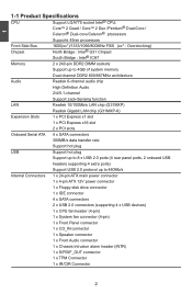
... Audio Realtek 6-channel audio chip High Definition Audio 2/4/5.1-channel Support Jack-Sensing function LAN Realtek 10/100Mb/s LAN chip (G31MXP) Realtek Gigabit LAN chip (G31MXP-K) Expansion Slots 1 x PCI Express x1 slot 1 x PCI Express x16 slot 2 x PCI slots Onboard Serial ATA... 4 x SATA connectors 300MB/s data transfer rate Support hot plug USB Support hot plug Support up to 8 x USB 2.0 ports (4 rear panel ports, 2 onboard...
... Audio Realtek 6-channel audio chip High Definition Audio 2/4/5.1-channel Support Jack-Sensing function LAN Realtek 10/100Mb/s LAN chip (G31MXP) Realtek Gigabit LAN chip (G31MXP-K) Expansion Slots 1 x PCI Express x1 slot 1 x PCI Express x16 slot 2 x PCI slots Onboard Serial ATA... 4 x SATA connectors 300MB/s data transfer rate Support hot plug USB Support hot plug Support up to 8 x USB 2.0 ports (4 rear panel ports, 2 onboard...

English Manual.
Page 10
1 Back Panel 1 x PS/2 keyboard port Connectors 1 x PS/2 mouse port 1 x Serial Port 1 x Parallel Port 4 x USB 2.0 ports 1 x RJ-45 LAN port 1 x VGA port 6-channel Audio ports Hardware Monitor System ...
1 Back Panel 1 x PS/2 keyboard port Connectors 1 x PS/2 mouse port 1 x Serial Port 1 x Parallel Port 4 x USB 2.0 ports 1 x RJ-45 LAN port 1 x VGA port 6-channel Audio ports Hardware Monitor System ...

English Manual.
Page 11
... 16. SATA Connectors 19. Speaker Connector 21. DDR2 DIMM Slots 24. PCI Express x1 Slot 6. South Bridge: Intel® ICH7 17. SYS_FAN Header 12. Front Panel Connector 18. Front Audio Connector 9. LGA 775 CPU Socket 27. PCI Express x16 Slot 7. S/PDIF_OUT Connector 11. TPM Connecter 13. USBPW1357_1 Jumper 3. CPU_FAN Header 25...
... 16. SATA Connectors 19. Speaker Connector 21. DDR2 DIMM Slots 24. PCI Express x1 Slot 6. South Bridge: Intel® ICH7 17. SYS_FAN Header 12. Front Panel Connector 18. Front Audio Connector 9. LGA 775 CPU Socket 27. PCI Express x16 Slot 7. S/PDIF_OUT Connector 11. TPM Connecter 13. USBPW1357_1 Jumper 3. CPU_FAN Header 25...

English Manual.
Page 12
... display devices, such as an USB keyboard/mouse, USB printer, USB flash drive and etc. 7. USB Ports The USB port supports the USB 2.0/1.1 specification. 1 1-3 Back Panel Connectors PS/2 Mouse Port 1 Parallel Port 3 LAN Port 8 Line In Line Out Microphone 2 4 PS/2 Keyboard Port Serial Port 5 VGA Port 6 USB Ports 7 Audio Ports...
... display devices, such as an USB keyboard/mouse, USB printer, USB flash drive and etc. 7. USB Ports The USB port supports the USB 2.0/1.1 specification. 1 1-3 Back Panel Connectors PS/2 Mouse Port 1 Parallel Port 3 LAN Port 8 Line In Line Out Microphone 2 4 PS/2 Keyboard Port Serial Port 5 VGA Port 6 USB Ports 7 Audio Ports...

English Manual.
Page 20
...slot cover from the slot. 13 After installing all expansion cards, replace the chassis cover. 6. Secure the card's metal bracket to the chassis back panel with the expansion card in your operating system. Install the driver provided with a screw. 5. Locate an expansion slot that supports your computer. Align ...Express x1 PCI Express x16 PCI Follow the steps below to release the card and then pull the card straight up from the chassis back panel. 2. Make sure the metal contacts on the card are completely inserted into the PCI Express x16 slot. Make sure the graphics card ...
...slot cover from the slot. 13 After installing all expansion cards, replace the chassis cover. 6. Secure the card's metal bracket to the chassis back panel with the expansion card in your operating system. Install the driver provided with a screw. 5. Locate an expansion slot that supports your computer. Align ...Express x1 PCI Express x16 PCI Follow the steps below to release the card and then pull the card straight up from the chassis back panel. 2. Make sure the metal contacts on the card are completely inserted into the PCI Express x16 slot. Make sure the graphics card ...
English Manual.
Page 22
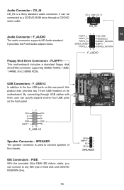
... speaker connector is a Sony standard audio connector, it can be connected to the four USB ports on the rear panel, this product also provides two 10-pin USB headers on the front panel. 12 VCC VCC D- SPKJ 1 EMPTY 2 NC 3 SPKJ 4 SPEAKER 15 IDE Connectors : PIDE With the provided Ultra DMA IDE ribbon...
... speaker connector is a Sony standard audio connector, it can be connected to the four USB ports on the rear panel, this product also provides two 10-pin USB headers on the front panel. 12 VCC VCC D- SPKJ 1 EMPTY 2 NC 3 SPKJ 4 SPEAKER 15 IDE Connectors : PIDE With the provided Ultra DMA IDE ribbon...

English Manual.
Page 23
... is directional with +/- The Power LED indicates the system's status. sign. Power Switch Connector (PWR-SW) Connect to be turned on the front panel of the chassis. Push this switch allows the system to the power button on and off after the system enters S3, S4 and S5 sleeping... state or power off . sign. 1 + HDD-LED - 2 + PWR-LED - This 2-pin connector is blinking; When the system is used to the chassis front panel IDE indicator LED. Serial ATA Connectors : SATA_1/2 The Serial ATA connector is in "PC Health Status" section of the chassis. Power LED Connector (PWR-LED...
... is directional with +/- The Power LED indicates the system's status. sign. Power Switch Connector (PWR-SW) Connect to be turned on the front panel of the chassis. Push this switch allows the system to the power button on and off after the system enters S3, S4 and S5 sleeping... state or power off . sign. 1 + HDD-LED - 2 + PWR-LED - This 2-pin connector is blinking; When the system is used to the chassis front panel IDE indicator LED. Serial ATA Connectors : SATA_1/2 The Serial ATA connector is in "PC Health Status" section of the chassis. Power LED Connector (PWR-LED...
English Manual.
Page 34
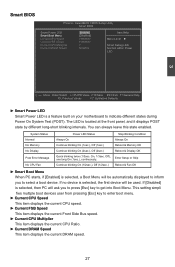
... F10:Save ESC:Exit F1:General Help F5: Previous Values F7: Optimized Defaults ► Smart Power LED Smart Power LED is located at the front panel, and it displays POST state by different long-short blinking intervals.
... F10:Save ESC:Exit F1:General Help F5: Previous Values F7: Optimized Defaults ► Smart Power LED Smart Power LED is located at the front panel, and it displays POST state by different long-short blinking intervals.
English Manual.
Page 58
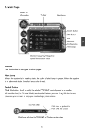
Exit FOX ONE Click here to go back to FOX ONE full screen Click here will simplify the whole FOX ONE control panel to a smaller information bar (i.e. Switch Button Click this bar to any place on your screen to help you can drag this button, it will drop ...
Exit FOX ONE Click here to go back to FOX ONE full screen Click here will simplify the whole FOX ONE control panel to a smaller information bar (i.e. Switch Button Click this bar to any place on your screen to help you can drag this button, it will drop ...
English Manual.
Page 59
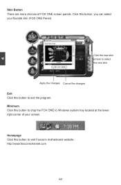
Click the new skin picture to exit the program. 4 Skin Button There are more choices of your favorite skin (FOX ONE Panel). Click this button to select the new skin Apply the changes Cancel the changes Exit Click this button, you can select your screen. Minimum Click this button to Windows system tray located at the lower right corner of FOX ONE screen panels. Homepage Click this button to drop the FOX ONE to visit Foxconn motherboard website : http://www.foxconnchannel.com 52
Click the new skin picture to exit the program. 4 Skin Button There are more choices of your favorite skin (FOX ONE Panel). Click this button to select the new skin Apply the changes Cancel the changes Exit Click this button, you can select your screen. Minimum Click this button to Windows system tray located at the lower right corner of FOX ONE screen panels. Homepage Click this button to drop the FOX ONE to visit Foxconn motherboard website : http://www.foxconnchannel.com 52
English Manual.
Page 62
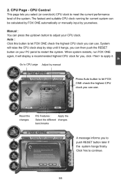
... A message informs you to push RESET button later if the system hangs finally. Manual : You can press the up/down button to adjust your PC panel to apply it hangs, you can use . System will display a recommended highest CPU clock for current system can then push the RESET button on your...
... A message informs you to push RESET button later if the system hangs finally. Manual : You can press the up/down button to adjust your PC panel to apply it hangs, you can use . System will display a recommended highest CPU clock for current system can then push the RESET button on your...
English Manual.
Page 63
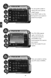
Run FOX ONE program again, it to your system. Click Yes to restart the computer. Now, your system to apply it will inform you the previous test found that 255MHz is the recommended CPU clock for your system. 4 You can see the system is running at a CPU clock of your system is raising CPU clock until the system hangs. Push RESET button on the front panel of 255MHz. 56
Run FOX ONE program again, it to your system. Click Yes to restart the computer. Now, your system to apply it will inform you the previous test found that 255MHz is the recommended CPU clock for your system. 4 You can see the system is running at a CPU clock of your system is raising CPU clock until the system hangs. Push RESET button on the front panel of 255MHz. 56
