
English Manual.
Page 23
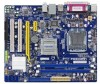
... on the front panel of the chassis. The Power LED indicates the system's status. Power Switch Connector (PWR-SW) Connect to the power LED indicator on the front panel of the BIOS Setup. These fans can be controlled and monitored in "PC Health Status" section of...supports infrared wireless transmitting and receiving device. 16 SATA _1/2 1 GND POWER SENSE CONTROL CPU_FAN/SYS_FAN 12 +5V +5VSB EMPTY CIRRX IRRX GND IRTX 9 10 CIRTX GND EMPTY IR/CIR RESET-SW PWR-SW NC EMPTY 9 10 FP1 2 Reset Switch (RESET-SW) Attach the connector to 300MB/s data transfer rate. 1 GND TX+...
... on the front panel of the chassis. The Power LED indicates the system's status. Power Switch Connector (PWR-SW) Connect to the power LED indicator on the front panel of the BIOS Setup. These fans can be controlled and monitored in "PC Health Status" section of...supports infrared wireless transmitting and receiving device. 16 SATA _1/2 1 GND POWER SENSE CONTROL CPU_FAN/SYS_FAN 12 +5V +5VSB EMPTY CIRRX IRRX GND IRTX 9 10 CIRTX GND EMPTY IR/CIR RESET-SW PWR-SW NC EMPTY 9 10 FP1 2 Reset Switch (RESET-SW) Attach the connector to 300MB/s data transfer rate. 1 GND TX+...


