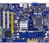
English Manual
Page 6
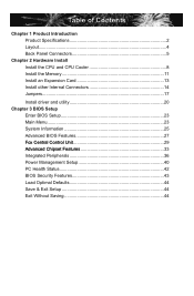
... Memory 11 Install an Expansion Card 13 Install other Internal Connectors 14 Jumpers 17 Install driver and utility 20 Chapter 3 BIOS Setup Enter BIOS Setup 23 Main Menu 23 System Information 25 Advanced BIOS Features 27 ......F.o.x..C.e.n.tr.a.l.C.o.n.t.ro.l.U..n.it 29 ......A.d.v.a.n.ce.d..C.h.ip.s.e.t.F.e.a.tu.r.e.s 33 Integrated Peripherals 36 Power Management Setup 40 PC Health...
... Memory 11 Install an Expansion Card 13 Install other Internal Connectors 14 Jumpers 17 Install driver and utility 20 Chapter 3 BIOS Setup Enter BIOS Setup 23 Main Menu 23 System Information 25 Advanced BIOS Features 27 ......F.o.x..C.e.n.tr.a.l.C.o.n.t.ro.l.U..n.it 29 ......A.d.v.a.n.ce.d..C.h.ip.s.e.t.F.e.a.tu.r.e.s 33 Integrated Peripherals 36 Power Management Setup 40 PC Health...
English Manual
Page 15
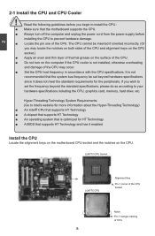
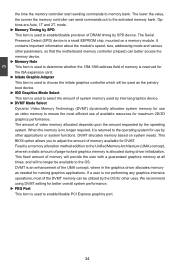
... Locate the alignment keys on the motherboard CPU socket and the notches on the computer if the CPU cooler is optimized for HT Technology ■ A BIOS that supports HT Technology and has it does not meet the standard requirements for the peripherals. If you begin to your hardware specifications including the...
... Locate the alignment keys on the motherboard CPU socket and the notches on the computer if the CPU cooler is optimized for HT Technology ■ A BIOS that supports HT Technology and has it does not meet the standard requirements for the peripherals. If you begin to your hardware specifications including the...
English Manual
Page 18
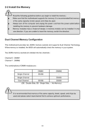
... installed in your system. DS/SS Dual Channel DS/SS DS/SS (DS : Double Side, SS : Single Side, - : No Memory) ! When memory is installed, the BIOS will automatically check the memory in only one direction. It is recommended that memory of DIMM modules are : Single Channel DIMM1 DS/SS DIMM2 - Single...
... installed in your system. DS/SS Dual Channel DS/SS DS/SS (DS : Double Side, SS : Single Side, - : No Memory) ! When memory is installed, the BIOS will automatically check the memory in only one direction. It is recommended that memory of DIMM modules are : Single Channel DIMM1 DS/SS DIMM2 - Single...
English Manual
Page 20
... to correctly install your computer. Remove the metal slot cover from the power outlet before installing an expansion card to make any required BIOS changes for your card. If necessary, go to BIOS Setup to prevent hardware damage. CAUTION 2 2-3 Install an Expansion Card ! ■ Make sure the motherboard supports the expansion card...
... to correctly install your computer. Remove the metal slot cover from the power outlet before installing an expansion card to make any required BIOS changes for your card. If necessary, go to BIOS Setup to prevent hardware damage. CAUTION 2 2-3 Install an Expansion Card ! ■ Make sure the motherboard supports the expansion card...
English Manual
Page 23
... connect to the Reset switch on the front panel of the chassis. Reset Switch (RESET-SW) Attach the connector to any IDE type of the BIOS Setup. The Power LED indicates the system's status. This 2-pin connector is off after the system enters S3, S4 and S5 sleeping states. 1 GND POWER...
... connect to the Reset switch on the front panel of the chassis. Reset Switch (RESET-SW) Attach the connector to any IDE type of the BIOS Setup. The Power LED indicates the system's status. This 2-pin connector is off after the system enters S3, S4 and S5 sleeping states. 1 GND POWER...
English Manual
Page 24
...;m��p��e�r�s�e��tt�in next chapter. Clear CMOS data is simply labeled as BIOS data, date, time information, hardware password...etc.). For any jumper setting. The steps to store the basic hardware information ...(such as "1". 2. It can change the jumper settings on the two pins to factory default when the BIOS settings were mistakenly modified. Jumper 1 Diagram 1 1 Definition 1-2 2-3 Description Set Pin 1 and Pin 2 closed Set Pin 2 and Pin 3 ...
...;m��p��e�r�s�e��tt�in next chapter. Clear CMOS data is simply labeled as BIOS data, date, time information, hardware password...etc.). For any jumper setting. The steps to store the basic hardware information ...(such as "1". 2. It can change the jumper settings on the two pins to factory default when the BIOS settings were mistakenly modified. Jumper 1 Diagram 1 1 Definition 1-2 2-3 Description Set Pin 1 and Pin 2 closed Set Pin 2 and Pin 3 ...

English Manual
Page 25
... using the connected USB devices. At the same time, a corresponding setting must not exceed the power supply capability (+5VSB) whether under normal condition or in BIOS as below: Set "CMOS Setup" -> "Power Management Setup" -> "USB Wake Up From S3" to wake up the computer from S3 and S4 sleep modes using...
... using the connected USB devices. At the same time, a corresponding setting must not exceed the power supply capability (+5VSB) whether under normal condition or in BIOS as below: Set "CMOS Setup" -> "Power Management Setup" -> "USB Wake Up From S3" to wake up the computer from S3 and S4 sleep modes using...
English Manual
Page 29
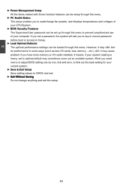
...■ P��C��H�e��a�lt�h��S�t�a�tu�s� ■ BIOS Security Features ■ L��o�a�d��O�p��ti�m�a��l �D�e�...(POST) process. 2. This chapter tells how to change the default CMOS settings. We do not guarantee the content of the BIOS parameters are also provided. This chapter includes the following cases occur : 1. Please visit our website for updated manual if it...
...■ P��C��H�e��a�lt�h��S�t�a�tu�s� ■ BIOS Security Features ■ L��o�a�d��O�p��ti�m�a��l �D�e�...(POST) process. 2. This chapter tells how to change the default CMOS settings. We do not guarantee the content of the BIOS parameters are also provided. This chapter includes the following cases occur : 1. Please visit our website for updated manual if it...

English Manual
Page 30
... item in the main menu is critical to the sub-menu. They all can be viewed or set up through this menu. ► Advanced BIOS Features The advanced system features can be responsible for the chipset can be changed through this menu, and the system performance can be optimized. ►...;�t�u��p� ► Integrated Peripherals E�x�it �W�ith�o�ut�S�av�in the BIOS Setup, and we shall not be set up through this menu. Main Menu The main menu allows you can be set up through this menu...
... item in the main menu is critical to the sub-menu. They all can be viewed or set up through this menu. ► Advanced BIOS Features The advanced system features can be responsible for the chipset can be changed through this menu, and the system performance can be optimized. ►...;�t�u��p� ► Integrated Peripherals E�x�it �W�ith�o�ut�S�av�in the BIOS Setup, and we shall not be set up through this menu. Main Menu The main menu allows you can be set up through this menu...
English Manual
Page 31
...Setup. ► Load Optimal Defaults The optimal performance settings can be loaded through this menu to prevent unauthorized use of your CPU/System. ► BIOS Security Features The Supervisor/User password can be setup through this menu. If you set a password, the system will ask you to read/change anything... and exit the setup. 24 It means, if your system loading is to adjust BIOS setting one by one, trial and error, to find out the best setting for your current system. ► Save & Exit Setup Save setting ...
...Setup. ► Load Optimal Defaults The optimal performance settings can be loaded through this menu to prevent unauthorized use of your CPU/System. ► BIOS Security Features The Supervisor/User password can be setup through this menu. If you set a password, the system will ask you to read/change anything... and exit the setup. 24 It means, if your system loading is to adjust BIOS setting one by one, trial and error, to find out the best setting for your current system. ► Save & Exit Setup Save setting ...
English Manual
Page 32
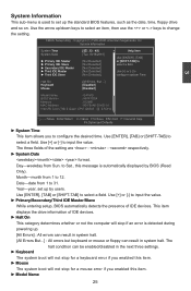
...ar�d D�is�ab�le�d] � Mo�us� e D� isa� ble�d] Model Name :G41MD BIOS Version :A81F1D04 Memory :512MB MAC Address :90-FB-A6-30-0D-91 Intel (R) Core (TM) 2 Quad CPU Q9300 @ 2.5GHz 3 Move ...25 Use [ENTER], [TAB] or [SHIFT-TAB] to input the value. ► Primary/Secondary/Third IDE Master/Slave While entering setup, BIOS automatically detects the presence of the setting are : : respectively. ► System Date format. System Information This sub-menu is detected during powering ...
...ar�d D�is�ab�le�d] � Mo�us� e D� isa� ble�d] Model Name :G41MD BIOS Version :A81F1D04 Memory :512MB MAC Address :90-FB-A6-30-0D-91 Intel (R) Core (TM) 2 Quad CPU Q9300 @ 2.5GHz 3 Move ...25 Use [ENTER], [TAB] or [SHIFT-TAB] to input the value. ► Primary/Secondary/Third IDE Master/Slave While entering setup, BIOS automatically detects the presence of the setting are : : respectively. ► System Date format. System Information This sub-menu is detected during powering ...

English Manual
Page 33
User can check this product. ► BIOS Version It displays the current BIOS version. 3 Model name of this information and discuss with the field service people if a BIOS upgrade is needed. ► Memory This item shows the information of the system memory, determined by POST(Power On Self Test) of the BIOS. ► MAC Address This item shows the onboard LAN MAC address. 26
User can check this product. ► BIOS Version It displays the current BIOS version. 3 Model name of this information and discuss with the field service people if a BIOS upgrade is needed. ► Memory This item shows the information of the system memory, determined by POST(Power On Self Test) of the BIOS. ► MAC Address This item shows the onboard LAN MAC address. 26
English Manual
Page 34
...also need to enable MPS 1.4 support if you should only leave it specifies the version of PCI cycle for a longer time. Advanced BIOS Features M�P�S �Re�vis�io� n 1�.4 He�lp�Ite�m PCI Latency Timer...will actually reduce performance as 1.1 only if you start facing problems like stuttering sound or a less responsive system, reduce the latency. Advanced BIOS Features CMOS Setup Utility - Higher values will use of POST messages. 27 MPS version 1.4 adds extended configuration tables for a secondary PCI...
...also need to enable MPS 1.4 support if you should only leave it specifies the version of PCI cycle for a longer time. Advanced BIOS Features M�P�S �Re�vis�io� n 1�.4 He�lp�Ite�m PCI Latency Timer...will actually reduce performance as 1.1 only if you start facing problems like stuttering sound or a less responsive system, reduce the latency. Advanced BIOS Features CMOS Setup Utility - Higher values will use of POST messages. 27 MPS version 1.4 adds extended configuration tables for a secondary PCI...

English Manual
Page 35
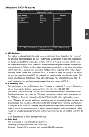
The available settings are: On (default) and Off. 28 3 ► Quick Boot While Enabled, this option allows BIOS to skip certain tests while booting, this will shorten the time needed to boot the system. ► Bootup Num-Lock This item defines if the keyboard Num Lock key is active when your system is started.
The available settings are: On (default) and Off. 28 3 ► Quick Boot While Enabled, this option allows BIOS to skip certain tests while booting, this will shorten the time needed to boot the system. ► Bootup Num-Lock This item defines if the keyboard Num Lock key is active when your system is started.

English Manual
Page 36
...clock of PCI Express slot. Copyright (C) 1985-2008, American Megatrends, Inc. It may enhance the graphics card speed. Super BIOS Protect function protects your BIOS from virus attack, there is used to auto detect PCI slot. Y��o�u��c�a�n��u&#...] PCI Express Clock [100] Help Item Move Enter:Select +/-/:Value F10:Save ESC:Exit F1:General Help F9:Optimized Defaults ► Smart BIOS / CPU Configuration / Voltage Options Press to go to change the value, or you enabled this function, it . ► Auto Detect PCI...
...clock of PCI Express slot. Copyright (C) 1985-2008, American Megatrends, Inc. It may enhance the graphics card speed. Super BIOS Protect function protects your BIOS from virus attack, there is used to auto detect PCI slot. Y��o�u��c�a�n��u&#...] PCI Express Clock [100] Help Item Move Enter:Select +/-/:Value F10:Save ESC:Exit F1:General Help F9:Optimized Defaults ► Smart BIOS / CPU Configuration / Voltage Options Press to go to change the value, or you enabled this function, it . ► Auto Detect PCI...
English Manual
Page 37
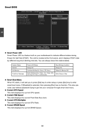
...to press [Del] key to enter setup or press [Esc] key to indicate different states during Power-On Self-Test (POST). Smart BIOS CMOS Setup Utility - Copyright (C) 1985-2008, American Megatrends, Inc. System Status Normal No Memory Post Error Message Power LED Status Always ... twice (1/3sec. On, 1/3sec. The LED is selected, then pressing [Esc] has no function. Off), one long On (1sec.), continuously. Smart BIOS Smart Power LED Smart Boot Menu Current CPU Speed Current FSB Speed Current CPU Multiplier Current DRAM Speed [Enabled] Help Item [Enabled] : 2.50GHz Options ...
...to press [Del] key to enter setup or press [Esc] key to indicate different states during Power-On Self-Test (POST). Smart BIOS CMOS Setup Utility - Copyright (C) 1985-2008, American Megatrends, Inc. System Status Normal No Memory Post Error Message Power LED Status Always ... twice (1/3sec. On, 1/3sec. The LED is selected, then pressing [Esc] has no function. Off), one long On (1sec.), continuously. Smart BIOS Smart Power LED Smart Boot Menu Current CPU Speed Current FSB Speed Current CPU Multiplier Current DRAM Speed [Enabled] Help Item [Enabled] : 2.50GHz Options ...

English Manual
Page 39
... ! Enhanced Intel SpeedStep® technology (EIST) allows the system to dynamically adjust processor voltage and core frequency, which can be met, including CPU, chipset, motherboard, BIOS and operation system. Please refer to 0.6V. 32
... ! Enhanced Intel SpeedStep® technology (EIST) allows the system to dynamically adjust processor voltage and core frequency, which can be met, including CPU, chipset, motherboard, BIOS and operation system. Please refer to 0.6V. 32
English Manual
Page 41
... of page-locked graphics memory is used as the primary boot device. ► IGD Graphics Mode Select This item is allocated during driver initialization. This BIOS option allows you to the operating system for running graphics applications. If a user is not performing any graphics-intensive operations, most efficient use by SPD...
... of page-locked graphics memory is used as the primary boot device. ► IGD Graphics Mode Select This item is allocated during driver initialization. This BIOS option allows you to the operating system for running graphics applications. If a user is not performing any graphics-intensive operations, most efficient use by SPD...

English Manual
Page 45
...:General Help F9:Optimized Defaults ► Serial Port1 Address This item is used to assign the I �te�m Serial Port1 Address [3F8/IRQ4] Allows BIOS to determine the transfer mode of the serial port 1. 38 SuperIO Configuration S�u�pe�rI�O�C�on�fi�gu...
...:General Help F9:Optimized Defaults ► Serial Port1 Address This item is used to assign the I �te�m Serial Port1 Address [3F8/IRQ4] Allows BIOS to determine the transfer mode of the serial port 1. 38 SuperIO Configuration S�u�pe�rI�O�C�on�fi�gu...
English Manual
Page 47
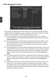
... latency sleeping state supported by RTC [S3 (STR)] Help Item [Power Off] [Enabled] Select the ACPI [Enabled] state used for initial boot operations within the BIOS to distinguish whether or not the boot is maintained. (also called Suspend to a minimum, it wakes. Power Management Setup CMOS Setup Utility - The system is...
... latency sleeping state supported by RTC [S3 (STR)] Help Item [Power Off] [Enabled] Select the ACPI [Enabled] state used for initial boot operations within the BIOS to distinguish whether or not the boot is maintained. (also called Suspend to a minimum, it wakes. Power Management Setup CMOS Setup Utility - The system is...


