
User manual
Page 1
H77MXV Series Motherboard User's Manual
H77MXV Series Motherboard User's Manual
User manual
Page 2
... for the environment and human health, which could otherwise be changed or modified at any time, Foxconn does not obligate itself to the physical motherboard for specific features. For more information about recycling of this product, please contact your local city ... that this product may be caused by inappropriate waste handling of this product is the intellectual property of Foxconn, Inc. All images are for H77MXV Series motherboard. Trademark: All trademarks are registered trademarks of respective manufacturers listed. By ensuring this product. CAUTIO Statement:...
... for the environment and human health, which could otherwise be changed or modified at any time, Foxconn does not obligate itself to the physical motherboard for specific features. For more information about recycling of this product, please contact your local city ... that this product may be caused by inappropriate waste handling of this product is the intellectual property of Foxconn, Inc. All images are for H77MXV Series motherboard. Trademark: All trademarks are registered trademarks of respective manufacturers listed. By ensuring this product. CAUTIO Statement:...

User manual
Page 3
declares that the product Motherboard H77MXV Series is in conformity with (reference to the specification under which conformity is declared in accordance with 89/336 EEC-EMC Directive) ■ EN 55022: ...
declares that the product Motherboard H77MXV Series is in conformity with (reference to the specification under which conformity is declared in accordance with 89/336 EEC-EMC Directive) ■ EN 55022: ...
User manual
Page 4
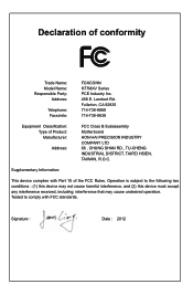
...714-738-8868 714-738-8838 Equipment Classification: Type of conformity Trade Name: Model Name: Responsible Party: Address: Telephone: Facsimile: FOXCONN H77MXV Series PCE Industry Inc. 458 E. Operation is subject to comply with Part 15 of the FCC Rules. Signature : Date : 2012... received, including interference that may cause undesired operation. Declaration of Product: Manufacturer: Address: FCC Class B Subassembly Motherboard HON HAI PRECISION INDUSTRY COMPANY LTD 66 , CHUNG SHAN RD., TU-CHENG INDUSTRIAL DISTRICT, TAIPEI HSIEN, TAIWAN, R.O.C. Lambert Rd.
...714-738-8868 714-738-8838 Equipment Classification: Type of conformity Trade Name: Model Name: Responsible Party: Address: Telephone: Facsimile: FOXCONN H77MXV Series PCE Industry Inc. 458 E. Operation is subject to comply with Part 15 of the FCC Rules. Signature : Date : 2012... received, including interference that may cause undesired operation. Declaration of Product: Manufacturer: Address: FCC Class B Subassembly Motherboard HON HAI PRECISION INDUSTRY COMPANY LTD 66 , CHUNG SHAN RD., TU-CHENG INDUSTRIAL DISTRICT, TAIPEI HSIEN, TAIWAN, R.O.C. Lambert Rd.
User manual
Page 5
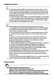
...is overclocked. It is a PCI Express x16 graphics card installed in contact with the connectors on the motherboard. Incorrect connections might damage the motherboard. ■ When handling the motherboard, avoid touching any metal leads or connectors. ■ If there is recommended to come in your system...■ If there is turned off before installing or removing CPU, memory, expansion cards or other peripherals. Normally it comes out as a motherboard, CPU or memory. ■ Ensure that the DC power supply is any installation steps or have a problem related to the use of ...
...is overclocked. It is a PCI Express x16 graphics card installed in contact with the connectors on the motherboard. Incorrect connections might damage the motherboard. ■ When handling the motherboard, avoid touching any metal leads or connectors. ■ If there is recommended to come in your system...■ If there is turned off before installing or removing CPU, memory, expansion cards or other peripherals. Normally it comes out as a motherboard, CPU or memory. ■ Ensure that the DC power supply is any installation steps or have a problem related to the use of ...
User manual
Page 8
Chapter 1 Product Introduction Thank you need for buying Foxconn H77MXV Series motherboard. This chapter includes the following information: ■ Product Specifications ■ Layout ■ Back Panel Connectors Foxconn products are engineered to maximize computing power, providing only what you for break-through performance.
Chapter 1 Product Introduction Thank you need for buying Foxconn H77MXV Series motherboard. This chapter includes the following information: ■ Product Specifications ■ Layout ■ Back Panel Connectors Foxconn products are engineered to maximize computing power, providing only what you for break-through performance.

User manual
Page 11
... 20 21 1. 4-pin ATX 12V Power Connector 2. Front USB 3.0 Header 14. Speaker Header 20. DDR3 DIMM Slot 23. CPU_FAN Header 24. SYS_FAN Header The above motherboard layout is for reference only, please refer to the physical...
... 20 21 1. 4-pin ATX 12V Power Connector 2. Front USB 3.0 Header 14. Speaker Header 20. DDR3 DIMM Slot 23. CPU_FAN Header 24. SYS_FAN Header The above motherboard layout is for reference only, please refer to the physical...

User manual
Page 14
... hardware installation process, including the installation of the CPU, memory, power supply, slots, pin headers and the mounting of these modules. Please refer to the motherboard layout prior to any installation and read the contents in this chapter carefully. This chapter includes the following information : ■ Install the CPU and CPU...
... hardware installation process, including the installation of the CPU, memory, power supply, slots, pin headers and the mounting of these modules. Please refer to the motherboard layout prior to any installation and read the contents in this chapter carefully. This chapter includes the following information : ■ Install the CPU and CPU...

User manual
Page 15
... that supports HT Technology and has it enabled Install the CPU Locate the alignment keys on the motherboard CPU socket and the notches on the computer if the CPU cooler is not recommended that the motherboard supports the CPU. ■ Always turn on the CPU. If you begin to install the CPU...
... that supports HT Technology and has it enabled Install the CPU Locate the alignment keys on the motherboard CPU socket and the notches on the computer if the CPU cooler is not recommended that the motherboard supports the CPU. ■ Always turn on the CPU. If you begin to install the CPU...

User manual
Page 17
... the bolts will be fixed as depicted in the picture. 3 2 1 4. Inadequately removing the CPU cooler may adhere to correctly install the CPU cooler on the motherboard. 1. Place the four bolts of the CPU cooler to the holes of CPU. 2. Turning push pin clockwise to the CPU FAN header on the... motherboard. Attach the 4-wire CPU cooler connector to its default position. Pull the push pin straight up. 3. Apply and spread an even thermal grease on the ...
... the bolts will be fixed as depicted in the picture. 3 2 1 4. Inadequately removing the CPU cooler may adhere to correctly install the CPU cooler on the motherboard. 1. Place the four bolts of the CPU cooler to the holes of CPU. 2. Turning push pin clockwise to the CPU FAN header on the... motherboard. Attach the 4-wire CPU cooler connector to its default position. Pull the push pin straight up. 3. Apply and spread an even thermal grease on the ...

User manual
Page 18
It is recommended that the motherboard supports the memory. If you are : DIMM1 DIMM2 Single Channel DS/SS - Dual Channel Memory Configuration Channel 0 : DIMM1 Channel 1 : DIMM2 The combinations of DIMM modules ...
It is recommended that the motherboard supports the memory. If you are : DIMM1 DIMM2 Single Channel DS/SS - Dual Channel Memory Configuration Channel 0 : DIMM1 Channel 1 : DIMM2 The combinations of DIMM modules ...
User manual
Page 20
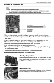
... to release the card and then pull the card straight up from the slot. 13 2-3 Install an Expansion Card HARDWARE INSTALLATION ■ Make sure the motherboard supports the expansion card. ■ Always turn off the computer and unplug the power cord from the chassis back panel. 2.
... to release the card and then pull the card straight up from the slot. 13 2-3 Install an Expansion Card HARDWARE INSTALLATION ■ Make sure the motherboard supports the expansion card. ■ Always turn off the computer and unplug the power cord from the chassis back panel. 2.

User manual
Page 21
... 3.3V 24 GND 12 PWR1 1 Pin No. 24 We recommend you using a 20-pin power supply, you are properly aligned with the connector on the motherboard. If you need to align the ATX power connector according to the picture. 20-Pin Power 4-pin ATX 12 V Power Connector: PWR2 Connect the 4-pin... and provides power to damage any device, make sure it is the ATX power supply connector. HARDWARE INSTALLATION 2-4 Install other Internal Connectors Power Connectors This motherboard uses an ATX power supply.
... 3.3V 24 GND 12 PWR1 1 Pin No. 24 We recommend you using a 20-pin power supply, you are properly aligned with the connector on the motherboard. If you need to align the ATX power connector according to the picture. 20-Pin Power 4-pin ATX 12 V Power Connector: PWR2 Connect the 4-pin... and provides power to damage any device, make sure it is the ATX power supply connector. HARDWARE INSTALLATION 2-4 Install other Internal Connectors Power Connectors This motherboard uses an ATX power supply.

User manual
Page 22
... using the power supply button. Power Switch Connector (PWR-SW) Connect to a security switch on and off . Push this connector. Front Panel Connector: FP1 This motherboard includes one connector for S/PDIF output. Power LED Connector (PWR-LED) Connect to the chassis front panel IDE indicator LED. It indicates the active status...
... using the power supply button. Power Switch Connector (PWR-SW) Connect to a security switch on and off . Push this connector. Front Panel Connector: FP1 This motherboard includes one connector for S/PDIF output. Power LED Connector (PWR-LED) Connect to the chassis front panel IDE indicator LED. It indicates the active status...

User manual
Page 23
... RX+ USB3.0 SS RXVCC EMPTY 1 2 USB 3.0 1 GND TX+ TXGND RXRX+ GND SATA_1/2 1 GND TX+ TXGND RXRX+ GND SATA_3/4 COM Connector : COM1 This motherboard supports one end to connect with the external RS232 device and another RS232 cable with a 9-pin D-sub connector at one serial RS232 COM port for... the additional USB 3.0 ports. Serial ATA 2.0 Connectors: SATA_3/4 These connectors are used to install the USB 3.0 driver in the motherboard. GND USB3.0 SS TX+ USB3.0 SS TX- User must purchase another end with 10-pin female connector to any of these connec- VCC DD+...
... RX+ USB3.0 SS RXVCC EMPTY 1 2 USB 3.0 1 GND TX+ TXGND RXRX+ GND SATA_1/2 1 GND TX+ TXGND RXRX+ GND SATA_3/4 COM Connector : COM1 This motherboard supports one end to connect with the external RS232 device and another RS232 cable with a 9-pin D-sub connector at one serial RS232 COM port for... the additional USB 3.0 ports. Serial ATA 2.0 Connectors: SATA_3/4 These connectors are used to install the USB 3.0 driver in the motherboard. GND USB3.0 SS TX+ USB3.0 SS TX- User must purchase another end with 10-pin female connector to any of these connec- VCC DD+...
User manual
Page 25
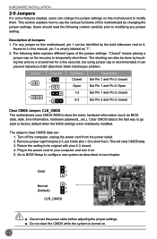
...different types of the jumper settings. This will clear CMOS data. 3. Plug in the power cord to configure new system as described in this motherboard by a screwdriver for a few seconds, but using jumper cap is simply labeled as BIOS data, date, time information, hardware password...etc.). ...Go to BIOS Setup to your computer and turn it . This section explains how to it on this motherboard, pin 1 can be done by touching two pins by changing the jumper settings. It can prevent hazardous ESD (Electrical Static Discharge) problem. ...
...different types of the jumper settings. This will clear CMOS data. 3. Plug in the power cord to configure new system as described in this motherboard by a screwdriver for a few seconds, but using jumper cap is simply labeled as BIOS data, date, time information, hardware password...etc.). ...Go to BIOS Setup to your computer and turn it . This section explains how to it on this motherboard, pin 1 can be done by touching two pins by changing the jumper settings. It can prevent hazardous ESD (Electrical Static Discharge) problem. ...

User manual
Page 26
HARDWARE INSTALLATION Intel® ME Jumper: PCH_ME_ENABLE This motherboard uses this jumper to improve management of corporate assets. CAUTIO 19 Intel® Management Engine (ME) is an embedded microcontroller located in Intel chipset. Set ...
HARDWARE INSTALLATION Intel® ME Jumper: PCH_ME_ENABLE This motherboard uses this jumper to improve management of corporate assets. CAUTIO 19 Intel® Management Engine (ME) is an embedded microcontroller located in Intel chipset. Set ...

User manual
Page 32
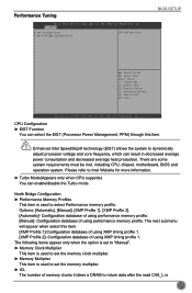
.... On, 1/3sec. If [Disabled] is a feature built on your computer through smart boot menu. This also prevents user without password trying to get into your motherboard to enter smart boot menu. Copyright (C) 2011 American Megatrends, Inc. ► Spread Spectrum If you had better disable it can significantly reduce the EMI (Electromagnetic...
.... On, 1/3sec. If [Disabled] is a feature built on your computer through smart boot menu. This also prevents user without password trying to get into your motherboard to enter smart boot menu. Copyright (C) 2011 American Megatrends, Inc. ► Spread Spectrum If you had better disable it can significantly reduce the EMI (Electromagnetic...
User manual
Page 34
... database of using performance memory profile. Options: [Automatic], [Manual], [XMP Profile 1], [XMP Profile 2]. [Automatic]- There are some system requirements must be met, including CPU, chipset, motherboard, BIOS and operation system. The following items appear only when the option is set to "Manual". ► Memory Clock Multiplier This item is used to...
... database of using performance memory profile. Options: [Automatic], [Manual], [XMP Profile 1], [XMP Profile 2]. [Automatic]- There are some system requirements must be met, including CPU, chipset, motherboard, BIOS and operation system. The following items appear only when the option is set to "Manual". ► Memory Clock Multiplier This item is used to...

User manual
Page 38
... Present ▶ SATA Port3:Not Present ▶ SATA Port4:Not Present → ←: Select Screen ↑ ↓: Select Item Enter: Select +/-: Change Opt. If your motherboard supporting AHCI, and you have a SATA device, which also supports AHCI, then you can select AHCI to get its best performance. [RAID] - This item is...
... Present ▶ SATA Port3:Not Present ▶ SATA Port4:Not Present → ←: Select Screen ↑ ↓: Select Item Enter: Select +/-: Change Opt. If your motherboard supporting AHCI, and you have a SATA device, which also supports AHCI, then you can select AHCI to get its best performance. [RAID] - This item is...


