

Installation Manual
Page 2
.... 1200 E. 151st Street Olathe, KS 66062 USA Aviation Panel-Mount Technical Support Line (Toll Free) 1.888.606.5482 Garmin (Europe) Ltd. Garmin aviation support and warranty information can be reproduced, copied, transmitted, disseminated, downloaded or stored in any storage medium, for any ... at www.flygarmin.com. Revision 1 Revision Date 08/04/17 RECORD OF REVISIONS Initial Release Description 190-02087-10 Rev. 1 GDL 51(R)/52(R) Installation Manual Page A Garmin hereby grants permission to download a single copy of this manual and of any revision to this manual onto a hard drive or ...
.... 1200 E. 151st Street Olathe, KS 66062 USA Aviation Panel-Mount Technical Support Line (Toll Free) 1.888.606.5482 Garmin (Europe) Ltd. Garmin aviation support and warranty information can be reproduced, copied, transmitted, disseminated, downloaded or stored in any storage medium, for any ... at www.flygarmin.com. Revision 1 Revision Date 08/04/17 RECORD OF REVISIONS Initial Release Description 190-02087-10 Rev. 1 GDL 51(R)/52(R) Installation Manual Page A Garmin hereby grants permission to download a single copy of this manual and of any revision to this manual onto a hard drive or ...

Installation Manual
Page 5
... Requirements 2-9 Section 3 Installation Procedure 3-1 3.1 Unpacking Unit...3-1 3.2 Wiring Harness Installation 3-1 3.3 Backshell Assembly...3-2 3.4 Coax Cable Installation...3-2 3.5 Equipment Mounting ...3-2 3.6 Continued Airworthiness 3-2 3.7 Antenna Installation ...3-3 3.8 Non-Garmin Antennas ...3-4 3.9 Garmin Antennas ...3-5 3.10 Post Installation Checkout 3-6 Section 4 System Interconnects 4-1 4.1 Pin Function List...4-1 Appendix A Outline and Installation Drawings A-1 Appendix B Interconnect Drawings B-1 190-02087-10 Rev. 1 GDL 51(R)/52(R) Installation Manual Page iii
... Requirements 2-9 Section 3 Installation Procedure 3-1 3.1 Unpacking Unit...3-1 3.2 Wiring Harness Installation 3-1 3.3 Backshell Assembly...3-2 3.4 Coax Cable Installation...3-2 3.5 Equipment Mounting ...3-2 3.6 Continued Airworthiness 3-2 3.7 Antenna Installation ...3-3 3.8 Non-Garmin Antennas ...3-4 3.9 Garmin Antennas ...3-5 3.10 Post Installation Checkout 3-6 Section 4 System Interconnects 4-1 4.1 Pin Function List...4-1 Appendix A Outline and Installation Drawings A-1 Appendix B Interconnect Drawings B-1 190-02087-10 Rev. 1 GDL 51(R)/52(R) Installation Manual Page iii
Installation Manual
Page 6
... personnel and/or avionics installation specialists using standard aviation maintenance practices in an aircraft. For questions, please contact Garmin Product Support at 1-888-606-5482. 1.2 Equipment Description The Garmin GDL 51/51R/52/52R products are remote mount versions that includes applicable internal GPS/ SXM/ADS-B antennas, and an internal battery. When in a portable form...
... personnel and/or avionics installation specialists using standard aviation maintenance practices in an aircraft. For questions, please contact Garmin Product Support at 1-888-606-5482. 1.2 Equipment Description The Garmin GDL 51/51R/52/52R products are remote mount versions that includes applicable internal GPS/ SXM/ADS-B antennas, and an internal battery. When in a portable form...

Installation Manual
Page 8
1.3 Technical Specifications 1.3.1 Physical Characteristics Table 1-1 GDL 51/52 Physical Characteristics Characteristic Height Width Depth Weight, GDL 51,52 Height w/Mounting Bracket Width w/Mounting Bracket Depth w/Mounting Bracket Weight w/Mounting Bracket Height w/Mounting Bracket and Non-Slip Pad Width w/Mounting Bracket and Non-Slip Pad Depth w/Mounting Bracket and Non-Slip Pad Weight w/Mounting Bracket and Non-Slip Pad Specification 1.30 inches (33.0 mm...
1.3 Technical Specifications 1.3.1 Physical Characteristics Table 1-1 GDL 51/52 Physical Characteristics Characteristic Height Width Depth Weight, GDL 51,52 Height w/Mounting Bracket Width w/Mounting Bracket Depth w/Mounting Bracket Weight w/Mounting Bracket Height w/Mounting Bracket and Non-Slip Pad Width w/Mounting Bracket and Non-Slip Pad Depth w/Mounting Bracket and Non-Slip Pad Weight w/Mounting Bracket and Non-Slip Pad Specification 1.30 inches (33.0 mm...
Installation Manual
Page 11
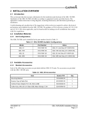
... and consideration of the suggestions in Table 2-1. The guidance of the GDL 5X/5XR. The appendices contain interconnect wiring diagrams, mounting dimensions, and information pertaining to A Style USB, Mass Storage, 0.5m Garmin P/N Qty 145-02489-00 1 253-00503-00 1 320-00239-53 1 320-00559-00 1 190-02087-10 Rev. 1 GDL 51(R)/52(R) Installation Manual Page 2-1
... and consideration of the suggestions in Table 2-1. The guidance of the GDL 5X/5XR. The appendices contain interconnect wiring diagrams, mounting dimensions, and information pertaining to A Style USB, Mass Storage, 0.5m Garmin P/N Qty 145-02489-00 1 253-00503-00 1 320-00239-53 1 320-00559-00 1 190-02087-10 Rev. 1 GDL 51(R)/52(R) Installation Manual Page 2-1

Installation Manual
Page 12
...Socket, Mil Crimp, Size 20, 20-24 AWG Garmin P/N 011-01855-01 330-00625-15 336-00022-02 Quantity 1 1 16 190-02087-10 Rev. 1 GDL 51(R)/52(R) Installation Manual Page 2-2 A single connector kit (010-12498-60) and mounting hardware (not provided) are required to 18 Pin ...Connector Cable Assembly, Data/Power with Mount (aera 660) Mounting Kit Portable Friction Mount Mounting Bracket Vehicle Power Cable, Micro-USB GA...
...Socket, Mil Crimp, Size 20, 20-24 AWG Garmin P/N 011-01855-01 330-00625-15 336-00022-02 Quantity 1 1 16 190-02087-10 Rev. 1 GDL 51(R)/52(R) Installation Manual Page 2-2 A single connector kit (010-12498-60) and mounting hardware (not provided) are required to 18 Pin ...Connector Cable Assembly, Data/Power with Mount (aera 660) Mounting Kit Portable Friction Mount Mounting Bracket Vehicle Power Cable, Micro-USB GA...

Installation Manual
Page 13
...unit for a limited length of the GDL 5XR. 2.4.1 Compass Safe Distance After reconfiguring the avionics in Appendix B. • For GDL 5X mounting bracket hardware (not provided): #8-32 ...locking nut for installing the GDL 5XR unit to the aircraft frame. • Push/Pull (that is not approved or supplied by Garmin. • Contact your ... data. 2.4.2 GDL 5X Battery Information If these guidelines are detailed in the cockpit panel, if the unit is mounted less than 30... days), store within the following temperature range: -4° to 122°F (-20° to the GDL 5XR...
...unit for a limited length of the GDL 5XR. 2.4.1 Compass Safe Distance After reconfiguring the avionics in Appendix B. • For GDL 5X mounting bracket hardware (not provided): #8-32 ...locking nut for installing the GDL 5XR unit to the aircraft frame. • Push/Pull (that is not approved or supplied by Garmin. • Contact your ... data. 2.4.2 GDL 5X Battery Information If these guidelines are detailed in the cockpit panel, if the unit is mounted less than 30... days), store within the following temperature range: -4° to 122°F (-20° to the GDL 5XR...
Installation Manual
Page 14
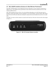
... Bluetooth wireless technology to create Connext® connections to display devices. Figure 2-1 GDL 5X Connext Antenna Location 190-02087-10 Rev. 1 GDL 51(R)/52(R) Installation Manual Page 2-4 For best performance, mount the GDL 5XR with the front of the Connext enabled devices. The GDL 5X Connext wireless antenna is located on aircraft body type (metal or...
... Bluetooth wireless technology to create Connext® connections to display devices. Figure 2-1 GDL 5X Connext Antenna Location 190-02087-10 Rev. 1 GDL 51(R)/52(R) Installation Manual Page 2-4 For best performance, mount the GDL 5XR with the front of the Connext enabled devices. The GDL 5X Connext wireless antenna is located on aircraft body type (metal or...

Installation Manual
Page 15
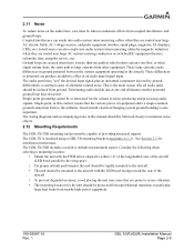
...If using larger barrel contacts, ensure that uses Bluetooth wireless technology, mount the devices apart from each other as much as possible away from all of the cables. 190-02087-10 Rev. 1 GDL 51(R)/52(R) Installation Manual Page 2-5 Allow adequate space for wire gauge guidance....Avoid routing near power sources (e.g. 400 Hz generators, trim motors, etc) or near heat sources. The GDL 5XR Connext wireless antenna is not possible, ensure that are mounted directly adjacent to each other . The installer will attenuate (decrease) the wireless signal. If the installation contains...
...If using larger barrel contacts, ensure that uses Bluetooth wireless technology, mount the devices apart from each other as much as possible away from all of the cables. 190-02087-10 Rev. 1 GDL 51(R)/52(R) Installation Manual Page 2-5 Allow adequate space for wire gauge guidance....Avoid routing near power sources (e.g. 400 Hz generators, trim motors, etc) or near heat sources. The GDL 5XR Connext wireless antenna is not possible, ensure that are mounted directly adjacent to each other . The installer will attenuate (decrease) the wireless signal. If the installation contains...
Installation Manual
Page 19
... the same path as large currents from nearby high-power equipment. 190-02087-10 Rev. 1 GDL 51(R)/52(R) Installation Manual Page 2-9 These differences in particular large heat loads from other equipment. Single-point grounding cannot be mounted to the aircraft with the FWD arrow aligned to within 1.0° of the longitudinal axis of...
... the same path as large currents from nearby high-power equipment. 190-02087-10 Rev. 1 GDL 51(R)/52(R) Installation Manual Page 2-9 These differences in particular large heat loads from other equipment. Single-point grounding cannot be mounted to the aircraft with the FWD arrow aligned to within 1.0° of the longitudinal axis of...

Installation Manual
Page 21
... Airworthiness Other than for regulatory checks, maintenance of the GDL 5X/5XR is not required. 3.3 Backshell Assembly Garmin's backshell gives the installer the ability to the desired length and install the connector. The GDL 5XR will be mounted on condition' only. Instructions for Continued Airworthiness (ICA)... the connector manufacturer's instructions for this product under 14 CFR Part 21 since the GDL 5X/5XR has received no FAA approval or endorsement. 190-02087-10 Rev. 1 GDL 51(R)/52(R) Installation Manual Page 3-2 If the connector is 'on the glare-shield. For ...
... Airworthiness Other than for regulatory checks, maintenance of the GDL 5X/5XR is not required. 3.3 Backshell Assembly Garmin's backshell gives the installer the ability to the desired length and install the connector. The GDL 5XR will be mounted on condition' only. Instructions for Continued Airworthiness (ICA)... the connector manufacturer's instructions for this product under 14 CFR Part 21 since the GDL 5X/5XR has received no FAA approval or endorsement. 190-02087-10 Rev. 1 GDL 51(R)/52(R) Installation Manual Page 3-2 If the connector is 'on the glare-shield. For ...

Installation Manual
Page 22
...should be connected to a Garmin Aera 660/795/796 or GDU 4XX display. Garmin recommends the antennas shown in Table 3-3 will work with a VSWR < 1.7:1 at 978 MHz and < 1.5:1 at least 3.3 feet away from all high power transmitting antennas. The GDL 5X can receive GPS position... 3-6. 3.7 Antenna Installation 3.7.1 ADS-B Antenna Installation The GDL 52 unit includes an ADS-B antenna. For best performance, mount the GPS, SiriusXM antennas on the bottom exterior of the GDL 5X to the GDL 52 via the MCX connector. The GDL 52R requires an external ADS-B antenna for GPS/SXM ...
...should be connected to a Garmin Aera 660/795/796 or GDU 4XX display. Garmin recommends the antennas shown in Table 3-3 will work with a VSWR < 1.7:1 at 978 MHz and < 1.5:1 at least 3.3 feet away from all high power transmitting antennas. The GDL 5X can receive GPS position... 3-6. 3.7 Antenna Installation 3.7.1 ADS-B Antenna Installation The GDL 52 unit includes an ADS-B antenna. For best performance, mount the GPS, SiriusXM antennas on the bottom exterior of the GDL 5X to the GDL 52 via the MCX connector. The GDL 52R requires an external ADS-B antenna for GPS/SXM ...
Installation Manual
Page 23
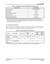
Table 3-4 XM Satellite Radio Antenna Minimum Requirements Characteristics Specifications Frequency Range 2332.5 to 2345 MHz Gain (Typical) 24 dB* Noise Figure
Table 3-4 XM Satellite Radio Antenna Minimum Requirements Characteristics Specifications Frequency Range 2332.5 to 2345 MHz Gain (Typical) 24 dB* Noise Figure

Installation Manual
Page 24
...) Flange, Magnetic, or Suction Cup Mounts (for in-cabin mounting) Flange, Magnetic, or Suction Cup Mounts (for in-cabin mounting) Flange, Magnetic, or Suction Cup Mounts (for detailed GPS antenna installation information. 3.9 Garmin Antennas NOTE See the G3X/G3X Touch Installation Manual (190-01115-01) for in-cabin mounting) 190-02087-10 Rev. 1 GDL 51(R)/52(R) Installation Manual Page 3-5
...) Flange, Magnetic, or Suction Cup Mounts (for in-cabin mounting) Flange, Magnetic, or Suction Cup Mounts (for in-cabin mounting) Flange, Magnetic, or Suction Cup Mounts (for detailed GPS antenna installation information. 3.9 Garmin Antennas NOTE See the G3X/G3X Touch Installation Manual (190-01115-01) for in-cabin mounting) 190-02087-10 Rev. 1 GDL 51(R)/52(R) Installation Manual Page 3-5

Installation Manual
Page 31
METRIC VALUES ARE FOR REFERENCE ONLY. 2. MOUNTING HOLES ARE FOR #8 100° FLAT HEAD SCREWS. DIMENSIONS ARE NOMINAL AND TOLERANCES ARE NOT IMPLIED UNLESS SPECIFICALLY STATED. 3. APPENDIX A OUTLINE AND INSTALLATION DRAWINGS WITH MOUNTING BRACKET 3.52 89.5 2X 1.188 30.16 .177 4.50 THRU ALL .344 8.74 X 100° NOTE 3 2X 1.500 38.10 190-02087-10 Rev. 1 1.51 38.3 5.26 133.6 NOTES: 1. Figure A-1.2 GDL 51/52 with Mounting Bracket Outline and Installation Drawing GDL 51(R)/52(R) Installation Manual Page A-2 DIMENSIONS: INCHES[mm].
METRIC VALUES ARE FOR REFERENCE ONLY. 2. MOUNTING HOLES ARE FOR #8 100° FLAT HEAD SCREWS. DIMENSIONS ARE NOMINAL AND TOLERANCES ARE NOT IMPLIED UNLESS SPECIFICALLY STATED. 3. APPENDIX A OUTLINE AND INSTALLATION DRAWINGS WITH MOUNTING BRACKET 3.52 89.5 2X 1.188 30.16 .177 4.50 THRU ALL .344 8.74 X 100° NOTE 3 2X 1.500 38.10 190-02087-10 Rev. 1 1.51 38.3 5.26 133.6 NOTES: 1. Figure A-1.2 GDL 51/52 with Mounting Bracket Outline and Installation Drawing GDL 51(R)/52(R) Installation Manual Page A-2 DIMENSIONS: INCHES[mm].

Installation Manual
Page 32
APPENDIX A OUTLINE AND INSTALLATION DRAWINGS WITH MOUNTING BRACKET & NON-SLIP PAD ACCESSOSRY 5.50 139.7 190-02087-10 Rev. 1 1.65 41.9 7.50 190.5 Figure A-1.3 GDL 51/52 with Mounting Bracket and Pad Outline and Installation Drawing GDL 51(R)/52(R) Installation Manual Page A-3
APPENDIX A OUTLINE AND INSTALLATION DRAWINGS WITH MOUNTING BRACKET & NON-SLIP PAD ACCESSOSRY 5.50 139.7 190-02087-10 Rev. 1 1.65 41.9 7.50 190.5 Figure A-1.3 GDL 51/52 with Mounting Bracket and Pad Outline and Installation Drawing GDL 51(R)/52(R) Installation Manual Page A-3

Installation Manual
Page 33
...2. CENTER OF GRAVITY (C.O.G.) LOCATION SHOWN IS WITHOUT CONNECTOR KIT INSTALLED. 4. MOUNTING HOLES FOR #6 100° FLAT HEAD SCREWS. NOTE 3 3X 2.215 56.26 .285 7.24 GDL 51R=3.20[81.3] GDL 52R=3.08 78.2 C.O.G. DIMENSIONS ARE NOMINAL AND TOLERANCES ARE NOT IMPLIED UNLESS... SPECIFICALLY STATED. 3. Figure A-2.1 GDL 51R/52R Outline and Installation Drawing 190-02087-10 Rev. 1 GDL 51(R)/52(R) Installation Manual Page A-4 NOTE 3 CONNECTOR SHOWN BROKEN OUT TO REVEAL MOUNTING HOLE GDL...
...2. CENTER OF GRAVITY (C.O.G.) LOCATION SHOWN IS WITHOUT CONNECTOR KIT INSTALLED. 4. MOUNTING HOLES FOR #6 100° FLAT HEAD SCREWS. NOTE 3 3X 2.215 56.26 .285 7.24 GDL 51R=3.20[81.3] GDL 52R=3.08 78.2 C.O.G. DIMENSIONS ARE NOMINAL AND TOLERANCES ARE NOT IMPLIED UNLESS... SPECIFICALLY STATED. 3. Figure A-2.1 GDL 51R/52R Outline and Installation Drawing 190-02087-10 Rev. 1 GDL 51(R)/52(R) Installation Manual Page A-4 NOTE 3 CONNECTOR SHOWN BROKEN OUT TO REVEAL MOUNTING HOLE GDL...


