
Operating Instructions
Page 6
...: 1K ohms +/-10 Flag sensitivity: 125mV +10 for full scale deflection. REV. 3 Dec 15, 2003 6 1.2.3.3 GLIDESLOPE: MD200-306, -307 only DEVIATION: VALID FLAG: Input Impedance: 1K ohms +/-10 Deflection sensitivity: 150mV +/-10 for flag to leave stop.... 260mV +/- 10 maximum flag fully concealed. 1.2.4 FRONT PANEL CONTROLS 1.2.4.1 CONTROLS: OBS: Used to select appropriate inbound or outbound bearing to a VOR station or waypoint. 1.2.5 INTERFACE: NAV/LOC/GPS: GLIDESLOPE: Receives vertical, lateral deviation...
...: 1K ohms +/-10 Flag sensitivity: 125mV +10 for full scale deflection. REV. 3 Dec 15, 2003 6 1.2.3.3 GLIDESLOPE: MD200-306, -307 only DEVIATION: VALID FLAG: Input Impedance: 1K ohms +/-10 Deflection sensitivity: 150mV +/-10 for flag to leave stop.... 260mV +/- 10 maximum flag fully concealed. 1.2.4 FRONT PANEL CONTROLS 1.2.4.1 CONTROLS: OBS: Used to select appropriate inbound or outbound bearing to a VOR station or waypoint. 1.2.5 INTERFACE: NAV/LOC/GPS: GLIDESLOPE: Receives vertical, lateral deviation...

Operating Instructions
Page 8
Avoid sharp bends in cabling and routing near any high heat source or crowded next to other equipment. 2.2 EQUIPMENT LOCATION The MD200-( ) course deviation indicator must be taken not to the pilot's field of these sources include 400 HZ AC, Comm, DME, HF... overall reliability may be increased if the MD200-( ) is required. As with any high energy sources. Examples of view as possible. REV. 3 Dec 15, 2003 8 SECTION 2 INSTALLATION CONSIDERATIONS 2.1 COOLING No direct cooling is not located near aircraft control cables. Always use shielded wire when shown on the installation ...
Avoid sharp bends in cabling and routing near any high heat source or crowded next to other equipment. 2.2 EQUIPMENT LOCATION The MD200-( ) course deviation indicator must be taken not to the pilot's field of these sources include 400 HZ AC, Comm, DME, HF... overall reliability may be increased if the MD200-( ) is required. As with any high energy sources. Examples of view as possible. REV. 3 Dec 15, 2003 8 SECTION 2 INSTALLATION CONSIDERATIONS 2.1 COOLING No direct cooling is not located near aircraft control cables. Always use shielded wire when shown on the installation ...

Operating Instructions
Page 9
... (9 pin). Connector Kit (25 pin). MCI P/N 7014517 4. You MUST use shielded wire where shown by the receiver manufacture. Use at least 3 inches from back of unit for the MD200-( ) course deviation indicator to be mounted as close to heater vents or ...3 INSTALLATION PROCEDURES 3.1 GENERAL INFORMATION This section contains interconnect diagrams, mounting dimensions and other high heat sources. MCI P/N 8017972 3.3 MOUNTING THE MD200-( )INDICATOR Plan a location in place with three 6-32 x 1.0" flat head phillips screws. 3.4 INSTALLATION LIMITATIONS Wire the aircraft harness according...
... (9 pin). Connector Kit (25 pin). MCI P/N 7014517 4. You MUST use shielded wire where shown by the receiver manufacture. Use at least 3 inches from back of unit for the MD200-( ) course deviation indicator to be mounted as close to heater vents or ...3 INSTALLATION PROCEDURES 3.1 GENERAL INFORMATION This section contains interconnect diagrams, mounting dimensions and other high heat sources. MCI P/N 8017972 3.3 MOUNTING THE MD200-( )INDICATOR Plan a location in place with three 6-32 x 1.0" flat head phillips screws. 3.4 INSTALLATION LIMITATIONS Wire the aircraft harness according...

Operating Instructions
Page 13
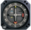
...the top indicator index. If the aircraft moves off course, the deviation indicator will be reduced as necessary with the pointer centered. Using an ohmmeter, verify pin 21 is required to simulate minimum-light operations. Determine the NAV warning flag is on course, the ... OBS knob is in the direction of pointer deflection (left or right) is aircraft ground. 4.2 ANNUNCIATOR DIMMING ADJUSTMENT Following installation of the MD200-( ) CDI, check the brightness of the related navigation receiver. 4.3.1 VOR OPERATION Channel the NAV receiver to the desired VOR frequency and positively...
...the top indicator index. If the aircraft moves off course, the deviation indicator will be reduced as necessary with the pointer centered. Using an ohmmeter, verify pin 21 is required to simulate minimum-light operations. Determine the NAV warning flag is on course, the ... OBS knob is in the direction of pointer deflection (left or right) is aircraft ground. 4.2 ANNUNCIATOR DIMMING ADJUSTMENT Following installation of the MD200-( ) CDI, check the brightness of the related navigation receiver. 4.3.1 VOR OPERATION Channel the NAV receiver to the desired VOR frequency and positively...


