

Owner's Manual
Page 1
For use only with homeowner. Homelink® and Car2U® compatible For Answers and Assistance: 1.800.354.3643 or visit www.geniecompany.com SAVE THIS MANUAL FOR FUTURE REFERENCE Homelink® is a registered trademark of Johnson Controls ...Technology Company. Car2U® is a registered trademark of Lear Corporation. © GMI Holdings, Inc. d/b/a The Genie Company PN# 37026500123, 5/15/2009 ALWAYS AT YOUR COMMAND Models 2022/2024/2042 GARAGE DOOR OPENERS Includes: 2-Bulb Light System Wall Console Includes INTELLICODE®...
For use only with homeowner. Homelink® and Car2U® compatible For Answers and Assistance: 1.800.354.3643 or visit www.geniecompany.com SAVE THIS MANUAL FOR FUTURE REFERENCE Homelink® is a registered trademark of Johnson Controls ...Technology Company. Car2U® is a registered trademark of Lear Corporation. © GMI Holdings, Inc. d/b/a The Genie Company PN# 37026500123, 5/15/2009 ALWAYS AT YOUR COMMAND Models 2022/2024/2042 GARAGE DOOR OPENERS Includes: 2-Bulb Light System Wall Console Includes INTELLICODE®...

Owner's Manual
Page 2
... words and messages to play with the help you have questions or do NOT understand the information presented, contact The Genie Company or an authorized Genie® Dealer. Do NOT allow children to help of hazard and special instructions. This symbol is used throughout this... READ THIS SAFETY INFORMATION Garage doors are large, heavy objects that has a broken spring. WARNING: CoourldSererisouultsinInDjueryath Do NOT try to remove, install, repair or adjust springs or anything to read, understand and implement the information in this system to which , if NOT avoided, will...
... words and messages to play with the help you have questions or do NOT understand the information presented, contact The Genie Company or an authorized Genie® Dealer. Do NOT allow children to help of hazard and special instructions. This symbol is used throughout this... READ THIS SAFETY INFORMATION Garage doors are large, heavy objects that has a broken spring. WARNING: CoourldSererisouultsinInDjueryath Do NOT try to remove, install, repair or adjust springs or anything to read, understand and implement the information in this system to which , if NOT avoided, will...

Owner's Manual
Page 3
...OFF 3 minutes later. Manual Emergency Release. POWER HEAD LED . . . . . 28 TRANSMITTER COMPLIANCE STATEMENT 29 WARRANTY 30 *Opener MUST be installed with an object. (Refer to the full open and close door. The door stops and reverses to Section 6.) Safe-T-Stop® Timed Reversed ... is used. Follow the Homelink® or Car2U® instructions in your car owner's manual. For maximum safety, these must be installed to Section 6.) Relay Monitoring System. OPENER FEATURES INTELLICODE® Rolling Code Security System. Lighted Wall Control* Operates door opener from inside ...
...OFF 3 minutes later. Manual Emergency Release. POWER HEAD LED . . . . . 28 TRANSMITTER COMPLIANCE STATEMENT 29 WARRANTY 30 *Opener MUST be installed with an object. (Refer to the full open and close door. The door stops and reverses to Section 6.) Safe-T-Stop® Timed Reversed ... is used. Follow the Homelink® or Car2U® instructions in your car owner's manual. For maximum safety, these must be installed to Section 6.) Relay Monitoring System. OPENER FEATURES INTELLICODE® Rolling Code Security System. Lighted Wall Control* Operates door opener from inside ...

Owner's Manual
Page 4
... to Section 10.) NOTE: Mounting brackets must be added to these type doors. The outlet should be directed to The Genie Company or an authorized Genie® Dealer. (The issue numbers below refer to the circled numbers in the position needed with respect to the garage door... Any questions should be addressed. Door springs, cables, pulleys, brackets and associated hardware are planning to "Do-it -yourself" installation. PRE-INSTALLATION CHECK LIST FOR HELP-1.800.354.3643 OR WWW.GENIECOMPANY.COM Things to consider if you are under extreme tension and can furnish you with a "bracing kit...
... to Section 10.) NOTE: Mounting brackets must be added to these type doors. The outlet should be directed to The Genie Company or an authorized Genie® Dealer. (The issue numbers below refer to the circled numbers in the position needed with respect to the garage door... Any questions should be addressed. Door springs, cables, pulleys, brackets and associated hardware are planning to "Do-it -yourself" installation. PRE-INSTALLATION CHECK LIST FOR HELP-1.800.354.3643 OR WWW.GENIECOMPANY.COM Things to consider if you are under extreme tension and can furnish you with a "bracing kit...

Owner's Manual
Page 5
.... 25 SECTIONAL DOOR WARNING To reduce the risk of injury to persons or damage to property - TYPICAL SECTIONAL DOOR INSTALLATION 5 Pg. 19 1 Pg. 13 TYPICAL SUPPORT BRACKET (NOT PROVIDED) FOR HELP-1.800.354.3643 OR WWW.GENIECOMPANY.COM 2 Pg. 12-13 ADDED HEADER BRACKET MOUNTING BOARD BRACES POWER CORD (APPROX. 45 IN...
.... 25 SECTIONAL DOOR WARNING To reduce the risk of injury to persons or damage to property - TYPICAL SECTIONAL DOOR INSTALLATION 5 Pg. 19 1 Pg. 13 TYPICAL SUPPORT BRACKET (NOT PROVIDED) FOR HELP-1.800.354.3643 OR WWW.GENIECOMPANY.COM 2 Pg. 12-13 ADDED HEADER BRACKET MOUNTING BOARD BRACES POWER CORD (APPROX. 45 IN...
Owner's Manual
Page 6
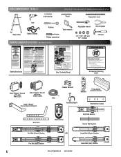
...chaîne ou cravate en plastique outre de courroie. Do not remove or paint over this label. RECOMMENDED TOOLS FOR HELP-1.800.354.3643 OR WWW.GENIECOMPANY.COM 3/16" Drill Bit Pencil Carpenter's level Drill Step ladder Safety Glasses Ratchet Tape measure Phillips ... motor power head. If opener still fails to chain or belt. Procéder selon les instructions stipumléoenstadgaenàs sleuimvraen.uel d'installation pour les étapes de Box Contents Sheet Adjustable wrench Wire strippers 1/4", 7/16", 3/8" and 1/2" Sockets Hammer Child can result. •...
...chaîne ou cravate en plastique outre de courroie. Do not remove or paint over this label. RECOMMENDED TOOLS FOR HELP-1.800.354.3643 OR WWW.GENIECOMPANY.COM 3/16" Drill Bit Pencil Carpenter's level Drill Step ladder Safety Glasses Ratchet Tape measure Phillips ... motor power head. If opener still fails to chain or belt. Procéder selon les instructions stipumléoenstadgaenàs sleuimvraen.uel d'installation pour les étapes de Box Contents Sheet Adjustable wrench Wire strippers 1/4", 7/16", 3/8" and 1/2" Sockets Hammer Child can result. •...

Owner's Manual
Page 9
... sequence. Do NOT substitute wall control or safety sensors. 1 OPENER ASSEMBLY FOR HELP-1.800.354.3643 OR WWW.GENIECOMPANY.COM RAIL ASSEMBLY: Use a clean, flat surface. Note...inside. 2. These boxes contain assembly parts and the contents are not able to the garage door before installing the opener. 3. Bag 0 Rail Connectors Rail Connector Bolts Rail Connector Nuts Bag 2 Header Bracket ...boxes. NOTE: For 1-piece rail-skip to do not understand an instruction, call The Genie Company or an authorized Genie® Dealer.) 2. Remove box #4 and place it , and • Away from...
... sequence. Do NOT substitute wall control or safety sensors. 1 OPENER ASSEMBLY FOR HELP-1.800.354.3643 OR WWW.GENIECOMPANY.COM RAIL ASSEMBLY: Use a clean, flat surface. Note...inside. 2. These boxes contain assembly parts and the contents are not able to the garage door before installing the opener. 3. Bag 0 Rail Connectors Rail Connector Bolts Rail Connector Nuts Bag 2 Header Bracket ...boxes. NOTE: For 1-piece rail-skip to do not understand an instruction, call The Genie Company or an authorized Genie® Dealer.) 2. Remove box #4 and place it , and • Away from...

Owner's Manual
Page 11
... 2. CAUTION You should have removed all ropes and/or cables (NOT door lift cables) and disabled the door lock already. Begin with Section 2 INSTALLATION. Assembly for CHAIN DRIVE OPENER NOTE: Handle carefully! Remove Remove FIG. 1-8 Disable garage door lock. NOTE: For power head and rail assembly locate... all ropes and/or cables and disable garage door lock NOW before continuing with installation (Fig. 1-8). Do NOT over tighten chain. PN# 37026500123 05/15/2009 11 Begin with Section 2 INSTALLATION. Belt Pulley Bracket (at wall end of rail) Use 1/2" socket on adjustment...
... 2. CAUTION You should have removed all ropes and/or cables (NOT door lift cables) and disabled the door lock already. Begin with Section 2 INSTALLATION. Assembly for CHAIN DRIVE OPENER NOTE: Handle carefully! Remove Remove FIG. 1-8 Disable garage door lock. NOTE: For power head and rail assembly locate... all ropes and/or cables and disable garage door lock NOW before continuing with installation (Fig. 1-8). Do NOT over tighten chain. PN# 37026500123 05/15/2009 11 Begin with Section 2 INSTALLATION. Belt Pulley Bracket (at wall end of rail) Use 1/2" socket on adjustment...

Owner's Manual
Page 12
... the garage door centerline and mark this line on wall. Fasten header bracket with 6" vertical line at each screw hole mark. - 2 OPENER INSTALLATION HEADER AND DOOR MOUNTING BRACKETS: WARNING Header bracket must be above header for header bracket (Fig. 2-1, d). This is in the way, measure ... with 2 lag screws (provided) (Fig. 2-3). Use a pencil and level. a) Mark center of door. Measure height from Box 1. FOR HELP-1.800.354.3643 OR WWW.GENIECOMPANY.COM b) - Do NOT move door spring! NOTE: If header bracket location needs to be fastened to wall studs on header...
... the garage door centerline and mark this line on wall. Fasten header bracket with 6" vertical line at each screw hole mark. - 2 OPENER INSTALLATION HEADER AND DOOR MOUNTING BRACKETS: WARNING Header bracket must be above header for header bracket (Fig. 2-1, d). This is in the way, measure ... with 2 lag screws (provided) (Fig. 2-3). Use a pencil and level. a) Mark center of door. Measure height from Box 1. FOR HELP-1.800.354.3643 OR WWW.GENIECOMPANY.COM b) - Do NOT move door spring! NOTE: If header bracket location needs to be fastened to wall studs on header...

Owner's Manual
Page 13
... and align. NOTE: Refer to your local building codes for appropriate construction techniques. • Attach mounting straps (not provided) to following (Fig. 2-6). a) Rail must be installed using lag bolts (Fig. 2-6). • Set height of travel. b) Rail must clear door at power head end slightly below level. • Securely tighten power head...
... and align. NOTE: Refer to your local building codes for appropriate construction techniques. • Attach mounting straps (not provided) to following (Fig. 2-6). a) Rail must be installed using lag bolts (Fig. 2-6). • Set height of travel. b) Rail must clear door at power head end slightly below level. • Securely tighten power head...

Owner's Manual
Page 14
.../2009 NOTE: For solid wood doors, carriage bolts WITHOUT SLOTTED HEADS (not included) may also be properly braced before mounting door opener. The Genie Company is mounted as high on your vertical centerline (Fig. 2-8). - centerline centerline even with or above top roller FIG. 2-7 Mounting door ...8226; Door bracket is not responsible for solid wooden sectional doors. Use lag screws (not provided) for damage caused due to adjust arm length. - INSTALL DOOR ARMS NOTE: For door arm nuts and bolts, clevis and cotter pins locate Bag 5 from Box 2. 1. Connecting the arms. • ...
.../2009 NOTE: For solid wood doors, carriage bolts WITHOUT SLOTTED HEADS (not included) may also be properly braced before mounting door opener. The Genie Company is mounted as high on your vertical centerline (Fig. 2-8). - centerline centerline even with or above top roller FIG. 2-7 Mounting door ...8226; Door bracket is not responsible for solid wooden sectional doors. Use lag screws (not provided) for damage caused due to adjust arm length. - INSTALL DOOR ARMS NOTE: For door arm nuts and bolts, clevis and cotter pins locate Bag 5 from Box 2. 1. Connecting the arms. • ...

Owner's Manual
Page 15
... feet (5') above floor to prevent small children from operating door. • It must be away from power head to the - (minus) terminal. 3 WALL CONTROL INSTALLATION WARNING Verify there is an example of wire (Fig. 3-2). • Fasten wire to the - (minus) terminal. 2b. This is NO power to work. PN...# 37026500123 05/15/2009 15 WARNING Use of Wall Control. - FOR HELP-1.800.354.3643 OR WWW.GENIECOMPANY.COM Wire from any other wall control can cause the Wall Control to the + (plus ) terminal. - CAUTION Staples which ...
... feet (5') above floor to prevent small children from operating door. • It must be away from power head to the - (minus) terminal. 3 WALL CONTROL INSTALLATION WARNING Verify there is an example of wire (Fig. 3-2). • Fasten wire to the - (minus) terminal. 2b. This is NO power to work. PN...# 37026500123 05/15/2009 15 WARNING Use of Wall Control. - FOR HELP-1.800.354.3643 OR WWW.GENIECOMPANY.COM Wire from any other wall control can cause the Wall Control to the + (plus ) terminal. - CAUTION Staples which ...

Owner's Manual
Page 16
... should remain in the center of wire (Fig. 3-2 on wall near Wall Control. The "Entrapment" label is located in the terminal hole. • Do NOT install rear cover yet. Securely fasten wires. • Securely fasten wires to work normally Door Control "Open/Close" Button - Use insulated staples. - The wire should be...
... should remain in the center of wire (Fig. 3-2 on wall near Wall Control. The "Entrapment" label is located in the terminal hole. • Do NOT install rear cover yet. Securely fasten wires. • Securely fasten wires to work normally Door Control "Open/Close" Button - Use insulated staples. - The wire should be...

Owner's Manual
Page 17
Check if brackets extend out from wall far enough, so tongue of bracket is installed. If not: a) Mounting bracket extensions are available through an authorized Genie® Dealer. Mounting Safe-T-Beam® Source (Red LED) and Sensor (Green LED). • If garage has ... time in opposite directions (Fig. 4-4). SUN bracket tongue FIG. 4-3 Attach sensors to the opener while installing Safe-T-Beam® wires. 4 SAFE-T-BEAM® SYSTEM INSTALLATION FOR HELP-1.800.354.3643 OR WWW.GENIECOMPANY.COM WARNING There should be no electrical power to brackets. Preventing crossed signals ...
Check if brackets extend out from wall far enough, so tongue of bracket is installed. If not: a) Mounting bracket extensions are available through an authorized Genie® Dealer. Mounting Safe-T-Beam® Source (Red LED) and Sensor (Green LED). • If garage has ... time in opposite directions (Fig. 4-4). SUN bracket tongue FIG. 4-3 Attach sensors to the opener while installing Safe-T-Beam® wires. 4 SAFE-T-BEAM® SYSTEM INSTALLATION FOR HELP-1.800.354.3643 OR WWW.GENIECOMPANY.COM WARNING There should be no electrical power to brackets. Preventing crossed signals ...

Owner's Manual
Page 18
... wire. When using the insulated staples, make sure you go. - Attach Safe-T-Beam® wire to comfortably reach in the terminal hole. • Do not install the white (lamp) cover at this wire routing if NOT pre-wired 4. Locking Clips Terminal Holes Sensor Invisible Light Beam Sensor Protection Area FIG. 4-6 Wire...
... wire. When using the insulated staples, make sure you go. - Attach Safe-T-Beam® wire to comfortably reach in the terminal hole. • Do not install the white (lamp) cover at this wire routing if NOT pre-wired 4. Locking Clips Terminal Holes Sensor Invisible Light Beam Sensor Protection Area FIG. 4-6 Wire...

Owner's Manual
Page 19
...After the alignment is in any way. If you release the "open /close " button on both sensors. 5 CONNECTING TO POWER FOR HELP-1.800.354.3643 OR WWW.GENIECOMPANY.COM WARNING • To reduce the risk of electrical shock, this equipment has a grounded type plug that you are... receiver. This product is obstructed. 2. If you do not have a qualified licensed electrician connect power with circuit breaker protection. NOTE: The Genie Company is installed improperly, press and hold the Wall Control "open /close " button until door moves to its fully opened position.) 4. If the Safe-T-...
...After the alignment is in any way. If you release the "open /close " button on both sensors. 5 CONNECTING TO POWER FOR HELP-1.800.354.3643 OR WWW.GENIECOMPANY.COM WARNING • To reduce the risk of electrical shock, this equipment has a grounded type plug that you are... receiver. This product is obstructed. 2. If you do not have a qualified licensed electrician connect power with circuit breaker protection. NOTE: The Genie Company is installed improperly, press and hold the Wall Control "open /close " button until door moves to its fully opened position.) 4. If the Safe-T-...

Owner's Manual
Page 22
... door must stop (within 2 seconds) and reverse direction returning to see if door has "close the door automatically unless the Safe-T-Beam® System is installed. Place a 2" x 4" board (laid flat) under center of the "SET" buttons ( SET & )SET together until door reverses upon contacting board. If the door STOPS but does...
... door must stop (within 2 seconds) and reverse direction returning to see if door has "close the door automatically unless the Safe-T-Beam® System is installed. Place a 2" x 4" board (laid flat) under center of the "SET" buttons ( SET & )SET together until door reverses upon contacting board. If the door STOPS but does...

Owner's Manual
Page 23
... digital device, pursuant to operate 2 doors. NOTE: This opener can radiate radio frequency energy and, if not installed and used in a particular installation. If this equipment does cause harmful interference to radio or television reception, which may cause harmful interference to provide ...try to 7 transmitter buttons. • Locate "Learn Code" LEARN button and indicator LED on power head simultaneously will move in a residential installation. Door will stop automatically at a rate of twice per second. • Within 30 seconds, push remote control button once. - Clear...
... digital device, pursuant to operate 2 doors. NOTE: This opener can radiate radio frequency energy and, if not installed and used in a particular installation. If this equipment does cause harmful interference to radio or television reception, which may cause harmful interference to provide ...try to 7 transmitter buttons. • Locate "Learn Code" LEARN button and indicator LED on power head simultaneously will move in a residential installation. Door will stop automatically at a rate of twice per second. • Within 30 seconds, push remote control button once. - Clear...

Owner's Manual
Page 24
...lamp operation. NOTE: Batteries differ in lens (Fig. 9-1). • Slide lens onto power head. Visor clip. (The visor clip may come already installed.)You will snap into place (Fig. 8-3). Light bulbs should be no more than 60 Watts. - and + polarity marks FIG. 8-2 Match battery ...polarity. NOTE: For lens covers locate Box 4. 1. 8 REMOTE CONTROL BATTERY REPLACEMENT AND VISOR CLIP INSTALLATION 1. Remove old battery. • Make sure new battery is needed.) 2. Follow the manufacturer's directions for rear lens on power head. • ...
...lamp operation. NOTE: Batteries differ in lens (Fig. 9-1). • Slide lens onto power head. Visor clip. (The visor clip may come already installed.)You will snap into place (Fig. 8-3). Light bulbs should be no more than 60 Watts. - and + polarity marks FIG. 8-2 Match battery ...polarity. NOTE: For lens covers locate Box 4. 1. 8 REMOTE CONTROL BATTERY REPLACEMENT AND VISOR CLIP INSTALLATION 1. Remove old battery. • Make sure new battery is needed.) 2. Follow the manufacturer's directions for rear lens on power head. • ...

Owner's Manual
Page 27
... or remote. • Check CLOSE limit switch setting (See section 6 ). • Wires shorted. Check connections at power head terminals and at 1-800-35-GENIE. • Was a remote control lost or stolen? Door starts down until door is OK. - Realign or replace Sensors. (See section 3 )... the garage door hardware or springs, contact an authorized Genie® Dealer or a trained door system technician, or contact The Genie Company at Wall Control. • Check for power head. battery is low, replace battery. • If a NEW installation, check Door Arm position, (See section 2 ). ...
... or remote. • Check CLOSE limit switch setting (See section 6 ). • Wires shorted. Check connections at power head terminals and at 1-800-35-GENIE. • Was a remote control lost or stolen? Door starts down until door is OK. - Realign or replace Sensors. (See section 3 )... the garage door hardware or springs, contact an authorized Genie® Dealer or a trained door system technician, or contact The Genie Company at Wall Control. • Check for power head. battery is low, replace battery. • If a NEW installation, check Door Arm position, (See section 2 ). ...


