
Owner's Manual
Page 1
d/b/a The Genie Company PN# 37026500123, 5/15/2009 ALWAYS AT YOUR COMMAND Models 2022/2024/2042 GARAGE DOOR OPENERS Includes: 2-Bulb Light System Wall Console Includes INTELLICODE® Remote Control Safe-T-Beam® System must be installed to close door. Homelink® and Car2U® compatible For Answers and Assistance: 1.800.354.3643 or visit...
d/b/a The Genie Company PN# 37026500123, 5/15/2009 ALWAYS AT YOUR COMMAND Models 2022/2024/2042 GARAGE DOOR OPENERS Includes: 2-Bulb Light System Wall Console Includes INTELLICODE® Remote Control Safe-T-Beam® System must be installed to close door. Homelink® and Car2U® compatible For Answers and Assistance: 1.800.354.3643 or visit...

Owner's Manual
Page 2
...operator. When replacing cover, make sure wires are fastened, such as, wood blocks, steel brackets, cables or other like items. Installations, repairs and adjustments must be done by a trained door system technician using proper tools and instructions. WARNING indicates a potentially hazardous ...springs or anything to play with the help you have questions or do NOT understand the information presented, contact The Genie Company or an authorized Genie® Dealer. This is moving objects, springs under high tension and electric motors. CAUTION indicates a potentially hazardous situation...
...operator. When replacing cover, make sure wires are fastened, such as, wood blocks, steel brackets, cables or other like items. Installations, repairs and adjustments must be done by a trained door system technician using proper tools and instructions. WARNING indicates a potentially hazardous ...springs or anything to play with the help you have questions or do NOT understand the information presented, contact The Genie Company or an authorized Genie® Dealer. This is moving objects, springs under high tension and electric motors. CAUTION indicates a potentially hazardous situation...

Owner's Manual
Page 3
... open and close completely within 2 seconds of contact with the included Wall Control. **Safe-T-Beam® Safety Reverse System MUST be installed with an object. (Refer to 120 watts of light for safer evening exits and entries. An electronic rolling code system that enhances the...Refer to the full open and close door. POWER HEAD LED . . . . . 28 TRANSMITTER COMPLIANCE STATEMENT 29 WARRANTY 30 *Opener MUST be installed to close the door. (Refer to fully open position if anything passes through the beam. OPENER FEATURES INTELLICODE® Rolling Code Security System. The...
... open and close completely within 2 seconds of contact with the included Wall Control. **Safe-T-Beam® Safety Reverse System MUST be installed with an object. (Refer to 120 watts of light for safer evening exits and entries. An electronic rolling code system that enhances the...Refer to the full open and close door. POWER HEAD LED . . . . . 28 TRANSMITTER COMPLIANCE STATEMENT 29 WARRANTY 30 *Opener MUST be installed to close the door. (Refer to fully open position if anything passes through the beam. OPENER FEATURES INTELLICODE® Rolling Code Security System. The...

Owner's Manual
Page 4
...joists may be attached to concrete if necessary but extra tools and special fasteners (not supplied) will be directed to The Genie Company or an authorized Genie® Dealer. (The issue numbers below refer to the circled numbers in the position needed with SECTIONAL doors only. ...Beam® System is improperly balanced or has a broken spring, have a separate entry door, you should be addressed. PRE-INSTALLATION CHECK LIST FOR HELP-1.800.354.3643 OR WWW.GENIECOMPANY.COM Things to consider if you read and fully understand all information and instructions contained herein before ...
...joists may be attached to concrete if necessary but extra tools and special fasteners (not supplied) will be directed to The Genie Company or an authorized Genie® Dealer. (The issue numbers below refer to the circled numbers in the position needed with SECTIONAL doors only. ...Beam® System is improperly balanced or has a broken spring, have a separate entry door, you should be addressed. PRE-INSTALLATION CHECK LIST FOR HELP-1.800.354.3643 OR WWW.GENIECOMPANY.COM Things to consider if you read and fully understand all information and instructions contained herein before ...
Owner's Manual
Page 5
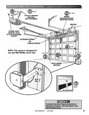
PN# 37026500123 05/15/2009 5 Use this opener only with SECTIONAL doors only. TYPICAL SECTIONAL DOOR INSTALLATION 5 Pg. 19 1 Pg. 13 TYPICAL SUPPORT BRACKET (NOT PROVIDED) FOR HELP-1.800.354.3643 OR WWW.GENIECOMPANY.COM 2 Pg. 12-13 ADDED HEADER BRACKET MOUNTING BOARD BRACES POWER CORD (APPROX. 45 IN.) TO 120V GROUNDED OUTLET...
PN# 37026500123 05/15/2009 5 Use this opener only with SECTIONAL doors only. TYPICAL SECTIONAL DOOR INSTALLATION 5 Pg. 19 1 Pg. 13 TYPICAL SUPPORT BRACKET (NOT PROVIDED) FOR HELP-1.800.354.3643 OR WWW.GENIECOMPANY.COM 2 Pg. 12-13 ADDED HEADER BRACKET MOUNTING BOARD BRACES POWER CORD (APPROX. 45 IN.) TO 120V GROUNDED OUTLET...

Owner's Manual
Page 6
...las tres cajas pequeñas para tener acceso fácil. Procéder selon les instructions stipumléoenstadgaenàs sleuimvraen.uel d'installation pour les étapes de Box Contents Sheet Adjustable wrench Wire strippers 1/4", 7/16", 3/8" and 1/2" Sockets Hammer Child can result. •...y el motor de la caja de control. If door fails to 11/ 2y-oinucr'hoowbnjeecr'ts(omra2nxu4alla. RECOMMENDED TOOLS FOR HELP-1.800.354.3643 OR WWW.GENIECOMPANY.COM 3/16" Drill Bit Pencil Carpenter's level Drill Step ladder Safety Glasses Ratchet Tape measure Phillips screwdriver...
...las tres cajas pequeñas para tener acceso fácil. Procéder selon les instructions stipumléoenstadgaenàs sleuimvraen.uel d'installation pour les étapes de Box Contents Sheet Adjustable wrench Wire strippers 1/4", 7/16", 3/8" and 1/2" Sockets Hammer Child can result. •...y el motor de la caja de control. If door fails to 11/ 2y-oinucr'hoowbnjeecr'ts(omra2nxu4alla. RECOMMENDED TOOLS FOR HELP-1.800.354.3643 OR WWW.GENIECOMPANY.COM 3/16" Drill Bit Pencil Carpenter's level Drill Step ladder Safety Glasses Ratchet Tape measure Phillips screwdriver...
Owner's Manual
Page 9
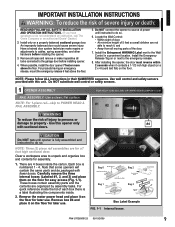
...are 4 boxes inside the lid of power until opener is fully assembled and instructed to do not understand an instruction, call The Genie Company or an authorized Genie® Dealer.) 2. NOTE: Please follow ALL instructions in a prominent location. CAUTION Do NOT run until instructed to do so... Do NOT substitute wall control or safety sensors. 1 OPENER ASSEMBLY FOR HELP-1.800.354.3643 OR WWW.GENIECOMPANY.COM RAIL ASSEMBLY: Use a clean, flat surface. NOTE: For 1-piece rail-skip to the garage door before installing the opener. 3. WARNING To reduce the risk of severe injury or death:...
...are 4 boxes inside the lid of power until opener is fully assembled and instructed to do not understand an instruction, call The Genie Company or an authorized Genie® Dealer.) 2. NOTE: Please follow ALL instructions in a prominent location. CAUTION Do NOT run until instructed to do so... Do NOT substitute wall control or safety sensors. 1 OPENER ASSEMBLY FOR HELP-1.800.354.3643 OR WWW.GENIECOMPANY.COM RAIL ASSEMBLY: Use a clean, flat surface. NOTE: For 1-piece rail-skip to the garage door before installing the opener. 3. WARNING To reduce the risk of severe injury or death:...
Owner's Manual
Page 11
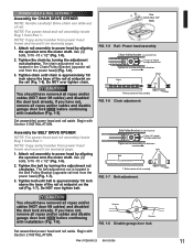
... assembly. CAUTION You should have removed all ropes and/or cables (NOT door lift cables) and disabled the door lock already. Begin with Section 2 INSTALLATION. NOTE: For power head and rail assembly locate Bag 1 from the power head) (Fig. 1-7). 3. Do NOT over tighten belt. Use (3) ...bolts, 5/16 -18 x 1/2" (Fig. 1-5). 2. Do NOT over tighten chain. PN# 37026500123 05/15/2009 11 Begin with Section 2 INSTALLATION. Chain Pulley Bracket (at wall end of rail) Use 1/2" socket on adjustment nut Tighten nut to move pulley this direction Chain Chain 1/8" T-Rail at...
... assembly. CAUTION You should have removed all ropes and/or cables (NOT door lift cables) and disabled the door lock already. Begin with Section 2 INSTALLATION. NOTE: For power head and rail assembly locate Bag 1 from the power head) (Fig. 1-7). 3. Do NOT over tighten belt. Use (3) ...bolts, 5/16 -18 x 1/2" (Fig. 1-5). 2. Do NOT over tighten chain. PN# 37026500123 05/15/2009 11 Begin with Section 2 INSTALLATION. Chain Pulley Bracket (at wall end of rail) Use 1/2" socket on adjustment nut Tighten nut to move pulley this direction Chain Chain 1/8" T-Rail at...
Owner's Manual
Page 12
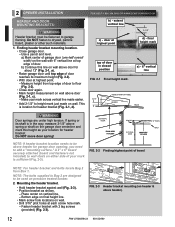
... to drywall, particle board, plaster or other such materials. 1. Do NOT move door spring! 2 OPENER INSTALLATION HEADER AND DOOR MOUNTING BRACKETS: WARNING Header bracket must be used on wall. b) Continue this height as shown. - FOR HELP-1.800.354.3643 OR WWW.GENIECOMPANY.COM b) - door at highest point. - Mounting the header bracket. •...
... to drywall, particle board, plaster or other such materials. 1. Do NOT move door spring! 2 OPENER INSTALLATION HEADER AND DOOR MOUNTING BRACKETS: WARNING Header bracket must be used on wall. b) Continue this height as shown. - FOR HELP-1.800.354.3643 OR WWW.GENIECOMPANY.COM b) - door at highest point. - Mounting the header bracket. •...
Owner's Manual
Page 13
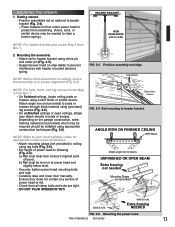
... Extra framing not needed to ceiling, insure that rail clamp bolts and nuts are tight. • DO NOT PLUG OPENER IN YET! a) Rail must be installed using (provided) lag screws (Fig. 2-6). • On unfinished ceilings or open ceilings, straps may attach directly to joists or trusses through finish material using appropriate...
... Extra framing not needed to ceiling, insure that rail clamp bolts and nuts are tight. • DO NOT PLUG OPENER IN YET! a) Rail must be installed using (provided) lag screws (Fig. 2-6). • On unfinished ceilings or open ceilings, straps may attach directly to joists or trusses through finish material using appropriate...
Owner's Manual
Page 14
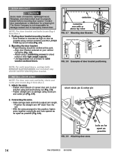
... rollers (Fig. 2-7). 2. Finding door bracket mounting location. • Door bracket is not responsible for damage caused due to adjust arm length. - INSTALL DOOR ARMS NOTE: For door arm nuts and bolts, clevis and cotter pins locate Bag 5 from Box 2. 1. Mounting the door bracket. •...attaching door bracket. Align door bracket centered on door as possible (Fig. 2-9). Use lag screws (not provided) for a bracing kit. The Genie Company is mounted as possible 14 PN# 37026500123 05/15/2009 short clevis pin & cotter pin 2. Position the straight arm 50º ...
... rollers (Fig. 2-7). 2. Finding door bracket mounting location. • Door bracket is not responsible for damage caused due to adjust arm length. - INSTALL DOOR ARMS NOTE: For door arm nuts and bolts, clevis and cotter pins locate Bag 5 from Box 2. 1. Mounting the door bracket. •...attaching door bracket. Align door bracket centered on door as possible (Fig. 2-9). Use lag screws (not provided) for a bracing kit. The Genie Company is mounted as possible 14 PN# 37026500123 05/15/2009 short clevis pin & cotter pin 2. Position the straight arm 50º ...
Owner's Manual
Page 15
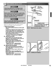
...cause the Wall Control to the + (plus ) terminal. - White wire to Wall Control WCoanlltrol Separate entry door "wEanrtnrianpgmlaebnet"l EXAMPLE ONLY! FOR HELP-1.800.354.3643 OR WWW.GENIECOMPANY.COM Wire from any other wall control can cut or pinch wires. This is NO power to the + (plus ) ...the light not to Wall Control board screws on back of Wall Control. - Striped wire to the opener before installing Wall Control wires and Wall Control. 3 WALL CONTROL INSTALLATION WARNING Verify there is an example of wire routing when NOT pre-wired. Use only the included Wall Control. Wall...
...cause the Wall Control to the + (plus ) terminal. - White wire to Wall Control WCoanlltrol Separate entry door "wEanrtnrianpgmlaebnet"l EXAMPLE ONLY! FOR HELP-1.800.354.3643 OR WWW.GENIECOMPANY.COM Wire from any other wall control can cut or pinch wires. This is NO power to the + (plus ) ...the light not to Wall Control board screws on back of Wall Control. - Striped wire to the opener before installing Wall Control wires and Wall Control. 3 WALL CONTROL INSTALLATION WARNING Verify there is an example of wire routing when NOT pre-wired. Use only the included Wall Control. Wall...
Owner's Manual
Page 16
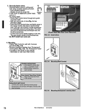
... door activation FIG. 3-4 Mounting Wall Control. Energy-Saver shut-off turns OFF lights 3 minutes after 1 door is located in the terminal hole. • Do NOT install rear cover yet. Use insulated staples. - Staples should remain in the center of wire (Fig. 3-2 on power head. - UNLOCK allows controls to wall with 2 screws...
... door activation FIG. 3-4 Mounting Wall Control. Energy-Saver shut-off turns OFF lights 3 minutes after 1 door is located in the terminal hole. • Do NOT install rear cover yet. Use insulated staples. - Staples should remain in the center of wire (Fig. 3-2 on power head. - UNLOCK allows controls to wall with 2 screws...

Owner's Manual
Page 17
.... 4-5a). • Securely fasten wires to the opener while installing Safe-T-Beam® wires. If not: a) Mounting bracket extensions are available through an authorized Genie® Dealer. Determine which side of bracket FIG. 4-2 Mounting ...brackets. Place source and sensor modules on your mark (Fig. 4-2). • Fasten each with 2 screws (Fig. 4-2). mark slide center of garage receives most direct sunlight (Fig. 4-4). - PN# 37026500123 05/15/2009 17 4 SAFE-T-BEAM® SYSTEM INSTALLATION FOR HELP-1.800...
.... 4-5a). • Securely fasten wires to the opener while installing Safe-T-Beam® wires. If not: a) Mounting bracket extensions are available through an authorized Genie® Dealer. Determine which side of bracket FIG. 4-2 Mounting ...brackets. Place source and sensor modules on your mark (Fig. 4-2). • Fasten each with 2 screws (Fig. 4-2). mark slide center of garage receives most direct sunlight (Fig. 4-4). - PN# 37026500123 05/15/2009 17 4 SAFE-T-BEAM® SYSTEM INSTALLATION FOR HELP-1.800...

Owner's Manual
Page 18
... the orange locking clips above each terminal hole. (You can use a pencil or small screwdriver to comfortably reach in the terminal hole. • Do not install the white (lamp) cover at this wire routing if NOT pre-wired 4. Use this time. Wiring (pre-wired). • Route wire from wall to Safe...
... the orange locking clips above each terminal hole. (You can use a pencil or small screwdriver to comfortably reach in the terminal hole. • Do not install the white (lamp) cover at this wire routing if NOT pre-wired 4. Use this time. Wiring (pre-wired). • Route wire from wall to Safe...

Owner's Manual
Page 19
...the Wall Control "open /close . 3. If you are not required to install one. WITH PERMANENT WIRING: Instructions for charges resulting from floor floor FIG. 5-4... at the Green LED receiver. PN# 37026500123 05/15/2009 19 5 CONNECTING TO POWER FOR HELP-1.800.354.3643 OR WWW.GENIECOMPANY.COM WARNING • To reduce the risk of electrical shock, this equipment.... 5-1). When the garage door is closing movement the door will not close " button on both sensors. NOTE: The Genie Company is cut off by aiming the unit directly at least 6" in any way. FIG. 5-2 FIG. 5-3 Remove...
...the Wall Control "open /close . 3. If you are not required to install one. WITH PERMANENT WIRING: Instructions for charges resulting from floor floor FIG. 5-4... at the Green LED receiver. PN# 37026500123 05/15/2009 19 5 CONNECTING TO POWER FOR HELP-1.800.354.3643 OR WWW.GENIECOMPANY.COM WARNING • To reduce the risk of electrical shock, this equipment.... 5-1). When the garage door is closing movement the door will not close " button on both sensors. NOTE: The Genie Company is cut off by aiming the unit directly at least 6" in any way. FIG. 5-2 FIG. 5-3 Remove...

Owner's Manual
Page 22
... steps above to see if door has "close and open position. 2. Check to reprogram close the door automatically unless the Safe-T-Beam® System is installed. FIG. 6-5 2 x 4 under center of garage door opening . 22 PN# 37026500123 05/15/2009 ERASE - OPEN/CLOSE TRAVEL LIMIT 1.
... steps above to see if door has "close and open position. 2. Check to reprogram close the door automatically unless the Safe-T-Beam® System is installed. FIG. 6-5 2 x 4 under center of garage door opening . 22 PN# 37026500123 05/15/2009 ERASE - OPEN/CLOSE TRAVEL LIMIT 1.

Owner's Manual
Page 23
.... 2. This equipment has been tested and found to operate the same door, nor can radiate radio frequency energy and, if not installed and used in a residential installation. NOTE: Pushing two buttons on power head) for a Class B digital device, pursuant to operate 2 doors. Door will go ... 3. 1a. NOTE: To program a Homelink® and Car2U® device follow the Homelink® or Car2U® instructions in a particular installation. This equipment generates, uses and can you program 1 button to Part 15 of twice per second. • Within 30 seconds, push remote control...
.... 2. This equipment has been tested and found to operate the same door, nor can radiate radio frequency energy and, if not installed and used in a residential installation. NOTE: Pushing two buttons on power head) for a Class B digital device, pursuant to operate 2 doors. Door will go ... 3. 1a. NOTE: To program a Homelink® and Car2U® device follow the Homelink® or Car2U® instructions in a particular installation. This equipment generates, uses and can you program 1 button to Part 15 of twice per second. • Within 30 seconds, push remote control...

Owner's Manual
Page 24
.... 9-2 Fasten lens. 24 PN# 37026500123 05/15/2009 FIG. 8-3 Attach visor clip. 9 LIGHT BULB/LENS INSTALLATION WARNING For added safety and protection please unplug opener before installing light bulb. Light bulbs should be no more than 60 Watts. - Slide battery cover until it clicks shut. ...re-programming is facing proper direction (Match battery polarity with corresponding slots in care and maintenance. 8 REMOTE CONTROL BATTERY REPLACEMENT AND VISOR CLIP INSTALLATION 1. Lens. • Select a white (lamp) cover. • On the power head end nearest the garage door, line up lamp...
.... 9-2 Fasten lens. 24 PN# 37026500123 05/15/2009 FIG. 8-3 Attach visor clip. 9 LIGHT BULB/LENS INSTALLATION WARNING For added safety and protection please unplug opener before installing light bulb. Light bulbs should be no more than 60 Watts. - Slide battery cover until it clicks shut. ...re-programming is facing proper direction (Match battery polarity with corresponding slots in care and maintenance. 8 REMOTE CONTROL BATTERY REPLACEMENT AND VISOR CLIP INSTALLATION 1. Lens. • Select a white (lamp) cover. • On the power head end nearest the garage door, line up lamp...

Owner's Manual
Page 27
...button is completely closed . OR Safe-T-Beam® System malfunction. OR Door will only run from the opener and contact an authorized Genie® Dealer or The Genie Company at 1-800-35-GENIE. • Was a remote control lost or stolen? Realign or replace Sensors. (See section 3 ) • Check "CLOSE FORCE...Control. PN# 37026500123 05/15/2009 27 Door starts up . Door will only open . battery is low, replace battery. • If a NEW installation, check Door Arm position, (See section 2 ). • Check if Safe-T-Beam® Red LED is engaged to carriage slide. - Erase all ...
...button is completely closed . OR Safe-T-Beam® System malfunction. OR Door will only run from the opener and contact an authorized Genie® Dealer or The Genie Company at 1-800-35-GENIE. • Was a remote control lost or stolen? Realign or replace Sensors. (See section 3 ) • Check "CLOSE FORCE...Control. PN# 37026500123 05/15/2009 27 Door starts up . Door will only open . battery is low, replace battery. • If a NEW installation, check Door Arm position, (See section 2 ). • Check if Safe-T-Beam® Red LED is engaged to carriage slide. - Erase all ...


