
Manual
Page 1
GA-8I915G-MF GA-8I915GM Intel® Pentium® 4 LGA775 Processor Motherboard User's Manual Rev. 2204 12ME-8I915GMF-2204 * The WEEE marking on the product indicates this product must not be disposed of with user's other household waste and must be handed over to a designated collection point for the recycling of waste electrical and electronic equipment!! * The WEEE marking applies only in European Union's member states.
GA-8I915G-MF GA-8I915GM Intel® Pentium® 4 LGA775 Processor Motherboard User's Manual Rev. 2204 12ME-8I915GMF-2204 * The WEEE marking on the product indicates this product must not be disposed of with user's other household waste and must be handed over to a designated collection point for the recycling of waste electrical and electronic equipment!! * The WEEE marking applies only in European Union's member states.
Manual
Page 6
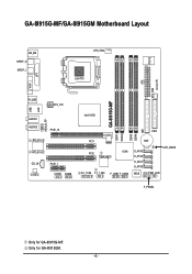
GA-8I915G-MF/GA-8I915GM Motherboard Layout IT8712 KB_MS SPDIF_O SPDIF_I CPU_FAN LGA775 SYS_FAN IR ATX VGA LPT R_USB ATX_12V USB LAN AZALIA_FP AUDIO1 AUDIO2 PCIE_16 RTL8110S RTL8100C CD_IN CODEC PCIE_1 COMA COMB GA-8I915G-MF DDR1 DDR2 Intel 915G IDE FDD DDR3 DDR4 PCI1 PCI2 ICH6 TSB43AB23 F2_1394 F1_1394 F_USB1 F_USB2 BAT S_ATA3 S_ATA2 S_ATA1 S_ATA0 CLR_CMOS BIOS PWR_LED F_PANEL Only for GA-8I915GM. - 6 - Only for GA-8I915G-MF.
GA-8I915G-MF/GA-8I915GM Motherboard Layout IT8712 KB_MS SPDIF_O SPDIF_I CPU_FAN LGA775 SYS_FAN IR ATX VGA LPT R_USB ATX_12V USB LAN AZALIA_FP AUDIO1 AUDIO2 PCIE_16 RTL8110S RTL8100C CD_IN CODEC PCIE_1 COMA COMB GA-8I915G-MF DDR1 DDR2 Intel 915G IDE FDD DDR3 DDR4 PCI1 PCI2 ICH6 TSB43AB23 F2_1394 F1_1394 F_USB1 F_USB2 BAT S_ATA3 S_ATA2 S_ATA1 S_ATA0 CLR_CMOS BIOS PWR_LED F_PANEL Only for GA-8I915GM. - 6 - Only for GA-8I915G-MF.

Manual
Page 7
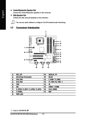
.../Mouse 3 IEEE1394 Center/Subwoofer Speaker Out Surround Speaker Out Side Speaker Out MIC Line-Out Line-In SPDIF In SPDIF Out PCICLK (33MHz) Only for GA-8I915GM. - 7 - Only for GA-8I915G-MF.
.../Mouse 3 IEEE1394 Center/Subwoofer Speaker Out Surround Speaker Out Side Speaker Out MIC Line-Out Line-In SPDIF In SPDIF Out PCICLK (33MHz) Only for GA-8I915GM. - 7 - Only for GA-8I915G-MF.

Manual
Page 10
...; Southbridge: Intel® ICH6 Š 4 DDR DIMM memory slots (supports up to standard PC architecture, a certain amount of memory is less than the stated amount. GA-8I915G-MF/GA-8I915GM Motherboard - 10 - Line Out (Front Speaker Out) ; Only for system usage and therefore the actual memory size is reserved for...
...; Southbridge: Intel® ICH6 Š 4 DDR DIMM memory slots (supports up to standard PC architecture, a certain amount of memory is less than the stated amount. GA-8I915G-MF/GA-8I915GM Motherboard - 10 - Line Out (Front Speaker Out) ; Only for system usage and therefore the actual memory size is reserved for...

Manual
Page 12
... into the socket in the wrong direction, the CPU will not insert properly. It is installed on the CPU socket to the CPU during installation.) GA-8I915G-MF/GA-8I915GM Motherboard - 12 - English 1-3 Installation of the CPU and Heatsink Before installing the CPU, please comply with the triangle and gently insert the CPU into position...
... into the socket in the wrong direction, the CPU will not insert properly. It is installed on the CPU socket to the CPU during installation.) GA-8I915G-MF/GA-8I915GM Motherboard - 12 - English 1-3 Installation of the CPU and Heatsink Before installing the CPU, please comply with the triangle and gently insert the CPU into position...

Manual
Page 14
... switched off to insert the module, please switch the direction. The motherboard supports DDR memory modules, whereby BIOS will automatically detect memory capacity and specifications. GA-8I915G-MF/GA-8I915GM Motherboard - 14 - Close the plastic clip at both edges of the DIMM slots to remove the DIMM module. Reverse the installation steps when you are...
... switched off to insert the module, please switch the direction. The motherboard supports DDR memory modules, whereby BIOS will automatically detect memory capacity and specifications. GA-8I915G-MF/GA-8I915GM Motherboard - 14 - Close the plastic clip at both edges of the DIMM slots to remove the DIMM module. Reverse the installation steps when you are...

Manual
Page 15
...in the same channel, the Dual Channel Technology will not operate when three DDR memory modules are installed; The following explanations due to work. GA-8I915G-MF/GA-8I915GM includes 4 DIMM sockets, and each Channel has two DIMM sockets as following: Channel A : DDR 1, DDR 2 Channel B : DDR...them will double. After operating the Dual Channel Technology, the bandwidth of Intel® chipset specifications. 1. English GA-8I915G-MF/GA-8I915GM supports the Dual Channel Technology. Hardware Installation We'll strongly recommend our user to slot two DDR memory modules into Channel A ...
...in the same channel, the Dual Channel Technology will not operate when three DDR memory modules are installed; The following explanations due to work. GA-8I915G-MF/GA-8I915GM includes 4 DIMM sockets, and each Channel has two DIMM sockets as following: Channel A : DDR 1, DDR 2 Channel B : DDR...them will double. After operating the Dual Channel Technology, the bandwidth of Intel® chipset specifications. 1. English GA-8I915G-MF/GA-8I915GM supports the Dual Channel Technology. Hardware Installation We'll strongly recommend our user to slot two DDR memory modules into Channel A ...

Manual
Page 16
... card is locked by following the steps outlined below: 1. Replace your expansion card by the small white-drawable bar. Install related driver from the computer. 3. GA-8I915G-MF/GA-8I915GM Motherboard - 16 - Press the expansion card firmly into the computer. 2. Please align the VGA card to the onboard PCI Express x 16 slot and press firmly...
... card is locked by following the steps outlined below: 1. Replace your expansion card by the small white-drawable bar. Install related driver from the computer. 3. GA-8I915G-MF/GA-8I915GM Motherboard - 16 - Press the expansion card firmly into the computer. 2. Please align the VGA card to the onboard PCI Express x 16 slot and press firmly...

Manual
Page 17
... SPDIF In feature only when your OS or device(s) vendors. Also make sure your OS does not support USB controller, please contact OS vendor for GA-8I915GM. - 17 - LAN Port The provided Internet connection is capable of a printer, scanner and other peripheral devices. Hardware Installation Line In Devices like CD-ROM, walkman...) and the keyboard o the lower port (purple). SPDIF_O (SPDIF Out) The SPDIF output is Gigabit Ethernet, providing data transfer speeds of 10/100Mbps. Only for GA-8I915G-MF. have a standard USB interface.
... SPDIF In feature only when your OS or device(s) vendors. Also make sure your OS does not support USB controller, please contact OS vendor for GA-8I915GM. - 17 - LAN Port The provided Internet connection is capable of a printer, scanner and other peripheral devices. Hardware Installation Line In Devices like CD-ROM, walkman...) and the keyboard o the lower port (purple). SPDIF_O (SPDIF Out) The SPDIF output is Gigabit Ethernet, providing data transfer speeds of 10/100Mbps. Only for GA-8I915G-MF. have a standard USB interface.
Manual
Page 18
Side Speaker Out Connect the side surround speakers to this connector. GA-8I915G-MF/GA-8I915GM Motherboard - 18 - You can use audio software to configure 2-/4-/6-/8-channel audio functioning. 1-7 Connectors Introduction 3 2 14 4 1 5 10 6 17 16 11 7 9 8 15 13 12 1) ATX_12V 10) AZALIA_FP ... / F_USB2 4) SYS_FAN 13) F1_1394 / F2_1394 5) FDD 14) IR 6) IDE 15) COMA / COMB 7) S_ATA0 / S_ATA1 / S_ATA2 / S_ATA3 16) CLR_CMOS 8) F_PANEL 17) BAT 9) PWR_LED Only for GA-8I915G-MF. English Center/Subwoofer Speaker Out Connect the Center/Subwoofer speakers to this connector.
Side Speaker Out Connect the side surround speakers to this connector. GA-8I915G-MF/GA-8I915GM Motherboard - 18 - You can use audio software to configure 2-/4-/6-/8-channel audio functioning. 1-7 Connectors Introduction 3 2 14 4 1 5 10 6 17 16 11 7 9 8 15 13 12 1) ATX_12V 10) AZALIA_FP ... / F_USB2 4) SYS_FAN 13) F1_1394 / F2_1394 5) FDD 14) IR 6) IDE 15) COMA / COMB 7) S_ATA0 / S_ATA1 / S_ATA2 / S_ATA3 16) CLR_CMOS 8) F_PANEL 17) BAT 9) PWR_LED Only for GA-8I915G-MF. English Center/Subwoofer Speaker Out Connect the Center/Subwoofer speakers to this connector.
Manual
Page 20
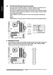
The types of the cable connects to the FDD drive. Please remember to connect the power to the cooler to the pin1 position. 34 33 2 1 GA-8I915G-MF/GA-8I915GM Motherboard - 20 - Most coolers are : 360KB, 720KB, 1.2MB, 1.44MB and 2.88MB. Please remember to connect the power to the CPU fan to connect the FDD ...
The types of the cable connects to the FDD drive. Please remember to connect the power to the cooler to the pin1 position. 34 33 2 1 GA-8I915G-MF/GA-8I915GM Motherboard - 20 - Most coolers are : 360KB, 720KB, 1.2MB, 1.44MB and 2.88MB. Please remember to connect the power to the CPU fan to connect the FDD ...

Manual
Page 22
... 2- Pin 3: NC Pin 4: Data(-) Open: Normal Operation Close: Reset Hardware System Open: Normal Operation Close: Power On/Off Pin 1: LED anode(+) Pin 2: LED cathode(-) NC GA-8I915G-MF/GA-8I915GM Motherboard - 22 - Message LED/ Power/ Sleep LED Power Switch Speaker Connector SPEAK- English 8) F_PANEL (Front Panel Jumper) Please connect the power LED, PC peaker, reset...
... 2- Pin 3: NC Pin 4: Data(-) Open: Normal Operation Close: Reset Hardware System Open: Normal Operation Close: Power On/Off Pin 1: LED anode(+) Pin 2: LED cathode(-) NC GA-8I915G-MF/GA-8I915GM Motherboard - 22 - Message LED/ Power/ Sleep LED Power Switch Speaker Connector SPEAK- English 8) F_PANEL (Front Panel Jumper) Please connect the power LED, PC peaker, reset...
Manual
Page 24
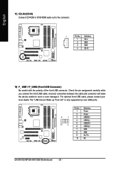
... device unable to the connector. 1 Pin No. Definition 1 Power 2 Power 9 1 3 USB DX- 4 USB Dy- 10 2 5 USB DX+ 6 USB Dy+ 7 GND 8 GND 9 No Pin 10 NC GA-8I915G-MF/GA-8I915GM Motherboard - 24 - Definition 1 CD-L 2 GND 3 GND 4 CD -R 12) F_ USB1 / F_USB2 (Front USB Connector) Be careful with the polarity of the front USB connector. Pin...
... device unable to the connector. 1 Pin No. Definition 1 Power 2 Power 9 1 3 USB DX- 4 USB Dy- 10 2 5 USB DX+ 6 USB Dy+ 7 GND 8 GND 9 No Pin 10 NC GA-8I915G-MF/GA-8I915GM Motherboard - 24 - Definition 1 CD-L 2 GND 3 GND 4 CD -R 12) F_ USB1 / F_USB2 (Front USB Connector) Be careful with the polarity of the front USB connector. Pin...
Manual
Page 26
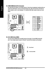
... cable, incorrect connection between the cable and connector will make the device unable to its default values by this jumper. 1 Open: Normal 1 Short :Clear CMOS GA-8I915G-MF/GA-8I915GM Motherboard - 26 - Default doesn't include the "Shunter" to prevent from improper use this jumper. For optional COM cable, please contact your local dealer. 2 10 1 9 Pin...
... cable, incorrect connection between the cable and connector will make the device unable to its default values by this jumper. 1 Open: Normal 1 Short :Clear CMOS GA-8I915G-MF/GA-8I915GM Motherboard - 26 - Default doesn't include the "Shunter" to prevent from improper use this jumper. For optional COM cable, please contact your local dealer. 2 10 1 9 Pin...

Manual
Page 30
..." to Setup. If you can't find the setting you to limit access to the system and Setup, or just to search the advanced option hidden. GA-8I915G-MF/GA-8I915GM Motherboard - 30 - CMOS Setup Utility-Copyright (C) 1984-2004 Award Software ` Standard CMOS Features ` Advanced BIOS Features ` Integrated Peripherals ` Power Management Setup ` PnP/PCI Configurations ` PC...
..." to Setup. If you can't find the setting you to limit access to the system and Setup, or just to search the advanced option hidden. GA-8I915G-MF/GA-8I915GM Motherboard - 30 - CMOS Setup Utility-Copyright (C) 1984-2004 Award Software ` Standard CMOS Features ` Advanced BIOS Features ` Integrated Peripherals ` Power Management Setup ` PnP/PCI Configurations ` PC...

Manual
Page 32
... the automatic detection step and allow for faster system start up. Enter the appropriate option based on this to 31 (or the maximum allowed in . GA-8I915G-MF/GA-8I915GM Motherboard - 32 - English 2-1 Standard CMOS Features Date (mm:dd:yy) Time (hh:mm:ss) CMOS Setup Utility-Copyright (C) 1984-2004 Award Software Standard CMOS Features...
... the automatic detection step and allow for faster system start up. Enter the appropriate option based on this to 31 (or the maximum allowed in . GA-8I915G-MF/GA-8I915GM Motherboard - 32 - English 2-1 Standard CMOS Features Date (mm:dd:yy) Time (hh:mm:ss) CMOS Setup Utility-Copyright (C) 1984-2004 Award Software Standard CMOS Features...
Manual
Page 34
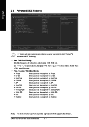
... to move it down the list. Use < > or < > to select a device, then press to exit this function. LAN Select your boot device priority by LAN. GA-8I915G-MF/GA-8I915GM Motherboard - 34 -
... to move it down the list. Use < > or < > to select a device, then press to exit this function. LAN Select your boot device priority by LAN. GA-8I915G-MF/GA-8I915GM Motherboard - 34 -

Manual
Page 36
...port. Set On-Chip SATA mode to Enhanced, the motherboard allows up to 6 HDDs to use up to Combined, you can use . GA-8I915G-MF/GA-8I915GM Motherboard - 36 - On-Chip SATA Mode Disabled Auto Combined Enhanced Non-Combined Disable this function. PATA mode. Set On-Chip SATA mode to...SATA will auto detect. (Default value) Set On-Chip SATA mode to 4 HDDs on the motherboard; 2 for SATA and the other for GA-8I915G-MF. English 2-3 Integrated Peripherals CMOS Setup Utility-Copyright (C) 1984-2004 Award Software Integrated Peripherals On-Chip Primary PCI IDE On-Chip SATA Mode x PATA...
...port. Set On-Chip SATA mode to Enhanced, the motherboard allows up to 6 HDDs to use up to Combined, you can use . GA-8I915G-MF/GA-8I915GM Motherboard - 36 - On-Chip SATA Mode Disabled Auto Combined Enhanced Non-Combined Disable this function. PATA mode. Set On-Chip SATA mode to...SATA will auto detect. (Default value) Set On-Chip SATA mode to 4 HDDs on the motherboard; 2 for SATA and the other for GA-8I915G-MF. English 2-3 Integrated Peripherals CMOS Setup Utility-Copyright (C) 1984-2004 Award Software Integrated Peripherals On-Chip Primary PCI IDE On-Chip SATA Mode x PATA...

Manual
Page 38
... as Enhanced Parallel Port. ECP Mode Use DMA 3 Set ECP Mode Use DMA to 3. (Default value) 1 Set ECP Mode Use DMA to seclect IR mode. GA-8I915G-MF/GA-8I915GM Motherboard - 38 - Enable onboard Serial port 2 and address is 3BC/IRQ7. Using Parallel port as ECP & EPP mode. Normal Set onboard I/O chip UART to Normal...
... as Enhanced Parallel Port. ECP Mode Use DMA 3 Set ECP Mode Use DMA to 3. (Default value) 1 Set ECP Mode Use DMA to seclect IR mode. GA-8I915G-MF/GA-8I915GM Motherboard - 38 - Enable onboard Serial port 2 and address is 3BC/IRQ7. Using Parallel port as ECP & EPP mode. Normal Set onboard I/O chip UART to Normal...

Manual
Page 40
... to the system, the system will return to power on the system. Full-On (Default value) When AC-power back to set the password here. GA-8I915G-MF/GA-8I915GM Motherboard - 40 - Enter Input password (from 1 to 5 characters to the system, the system always in "Off" state.
... to the system, the system will return to power on the system. Full-On (Default value) When AC-power back to set the password here. GA-8I915G-MF/GA-8I915GM Motherboard - 40 - Enter Input password (from 1 to 5 characters to the system, the system always in "Off" state.

