Manual
Page 10
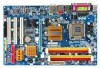
... Chipset Š Southbridge: Intel® ICH7 LAN Š Onboard Realtek RTL8111B chip (10/100/1000 Mbit) Audio Š Onboard Realtek ALC888 chip Š Supports High Definition Audio Š Supports 2 / 4 / 6 / 8 channel audio Š Supports S/PDIF In/Out connection Š Supports CD In connection Storage Š ICH7 Southbrigde - 1 FDD connector, allowing ...138; 1 CD In connector Š 1 S/PDIF In/Out connector Š 2 USB 2.0/1.1 connectors for additional 4 ports by cables Š 1 Chassis Intrusion connector Š 1 power LED connector GA-945G-DS3 Motherboard - 10 -
... Chipset Š Southbridge: Intel® ICH7 LAN Š Onboard Realtek RTL8111B chip (10/100/1000 Mbit) Audio Š Onboard Realtek ALC888 chip Š Supports High Definition Audio Š Supports 2 / 4 / 6 / 8 channel audio Š Supports S/PDIF In/Out connection Š Supports CD In connection Storage Š ICH7 Southbrigde - 1 FDD connector, allowing ...138; 1 CD In connector Š 1 S/PDIF In/Out connector Š 2 USB 2.0/1.1 connectors for additional 4 ports by cables Š 1 Chassis Intrusion connector Š 1 power LED connector GA-945G-DS3 Motherboard - 10 -

Manual
Page 19
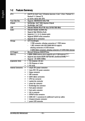
... It is not connected, the system will not start . otherwise, please do not remove it. 3 4 1 2 ATX_12V Pin No. 1 2 3 4 Definition GND GND +12V +12V 12 24 1 13 ATX Pin No. 1 2 3 4 5 6 7 8 9 10 11 12 Definition 3.3V 3.3V GND +5V GND +5V GND Power Good 5V SB(stand by +5V) +12V +12V(Only for 24...-pin ATX) 3.3V(Only for 24-pin ATX) Pin No. 13 14 15 16 17 18 19 20 21 22 23 24 Definition 3.3V -12V GND PS_ON(soft On/Off) GND GND GND -5V +5V +5V +5V (Only for 24-pin ATX) GND(Only for 24-pin ATX...
... It is not connected, the system will not start . otherwise, please do not remove it. 3 4 1 2 ATX_12V Pin No. 1 2 3 4 Definition GND GND +12V +12V 12 24 1 13 ATX Pin No. 1 2 3 4 5 6 7 8 9 10 11 12 Definition 3.3V 3.3V GND +5V GND +5V GND Power Good 5V SB(stand by +5V) +12V +12V(Only for 24...-pin ATX) 3.3V(Only for 24-pin ATX) Pin No. 13 14 15 16 17 18 19 20 21 22 23 24 Definition 3.3V -12V GND PS_ON(soft On/Off) GND GND GND -5V +5V +5V +5V (Only for 24-pin ATX) GND(Only for 24-pin ATX...
Manual
Page 20
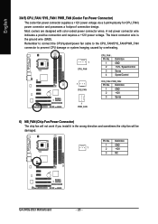
... power connector and possesses a foolproof connection design. A red power connector wire indicates a positive connection and requires a +12V power voltage. Definition 1 GND 2 +12V 3 Sense 6) NB_FAN (Chip Fan Power Connector) The chip fan will not work if you install it in the... or system hanging caused by overheating. 1 CPU_FAN 1 SYS_FAN 1 PWR_FAN CPU_FAN : Pin No. 1 2 3 4 Definition GND +12V / Speed Control Sense Speed Control SYS_FAN / PWR_FAN : Pin No. The black connector wire is the ground wire (GND). Definition 1 GND 1 2 +12V 3 NC GA-945G-DS3 Motherboard - 20 -
... power connector and possesses a foolproof connection design. A red power connector wire indicates a positive connection and requires a +12V power voltage. Definition 1 GND 2 +12V 3 Sense 6) NB_FAN (Chip Fan Power Connector) The chip fan will not work if you install it in the... or system hanging caused by overheating. 1 CPU_FAN 1 SYS_FAN 1 PWR_FAN CPU_FAN : Pin No. 1 2 3 4 Definition GND +12V / Speed Control Sense Speed Control SYS_FAN / PWR_FAN : Pin No. The black connector wire is the ground wire (GND). Definition 1 GND 1 2 +12V 3 NC GA-945G-DS3 Motherboard - 20 -
Manual
Page 22
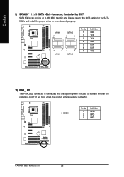
... on/off. SATAII0 7 1 SATAII2 7 1 1 7 SATAII1 1 7 SATAII3 Pin No. 1 2 3 4 5 6 7 Definition GND TXP TXN GND RXN RXP GND 10) PWR_LED The PWR_LED connector is connected with the system power indicator to 300 MB/s transfer rate. It will blink when the system enters suspend mode(S1). GA-945G-DS3 Motherboard - 22 - Please refer to the BIOS setting...
... on/off. SATAII0 7 1 SATAII2 7 1 1 7 SATAII1 1 7 SATAII3 Pin No. 1 2 3 4 5 6 7 Definition GND TXP TXN GND RXN RXP GND 10) PWR_LED The PWR_LED connector is connected with the system power indicator to 300 MB/s transfer rate. It will blink when the system enters suspend mode(S1). GA-945G-DS3 Motherboard - 22 - Please refer to the BIOS setting...
Manual
Page 24
... HD Audio: Pin No. 1 2 3 4 5 6 7 8 9 10 2 Definition MIC2_L GND MIC2_R -ACZ_DET LINE2_R FSENSE1 FAUDIO_JD No Pin LINE2_L FSENSE2 1 AC'97 Audio: Pin No. Definition 1 CD-L 1 2 GND 3 GND 4 CD-R GA-945G-DS3 Motherboard - 24 - Pin No. English 12) F_AUDIO (Front Audio Connector) This connector ...supports either HD (High Definition) or AC97 front panel audio module. Check the ...
... HD Audio: Pin No. 1 2 3 4 5 6 7 8 9 10 2 Definition MIC2_L GND MIC2_R -ACZ_DET LINE2_R FSENSE1 FAUDIO_JD No Pin LINE2_L FSENSE2 1 AC'97 Audio: Pin No. Definition 1 CD-L 1 2 GND 3 GND 4 CD-R GA-945G-DS3 Motherboard - 24 - Pin No. English 12) F_AUDIO (Front Audio Connector) This connector ...supports either HD (High Definition) or AC97 front panel audio module. Check the ...

Manual
Page 25
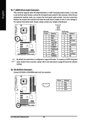
... S/PDIF output is capable of the SPDIF_IO connector. Use S/PDIF IN feature only when your local dealer. 2 10 1 9 Pin No. 1 2 3 4 5 6 7 8 9 10 Definition Power (5V) Power (5V) USB DXUSB DyUSB DX+ USB Dy+ GND GND No Pin NC - 25 - Check the pin assignment carefully while you connect the... the polarity of the front USB connector. Hardware Installation Use this feature only when your local dealer. 26 15 Pin No. 1 2 3 4 5 6 Definition Power No Pin SPDIF SPDIFI GND GND 15) F_ USB1 / F_USB2 (Front USB Connector) Be careful with the polarity of providing digital audio to external...
... S/PDIF output is capable of the SPDIF_IO connector. Use S/PDIF IN feature only when your local dealer. 2 10 1 9 Pin No. 1 2 3 4 5 6 7 8 9 10 Definition Power (5V) Power (5V) USB DXUSB DyUSB DX+ USB Dy+ GND GND No Pin NC - 25 - Check the pin assignment carefully while you connect the... the polarity of the front USB connector. Hardware Installation Use this feature only when your local dealer. 26 15 Pin No. 1 2 3 4 5 6 Definition Power No Pin SPDIF SPDIFI GND GND 15) F_ USB1 / F_USB2 (Front USB Connector) Be careful with the polarity of providing digital audio to external...
Manual
Page 26
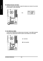
You can check the "Case Opened" status in BIOS Setup. Definition 1 1 Signal 2 GND 17) CLR_CMOS (Clear CMOS) You may clear the CMOS data to its default values by this header. To clear CMOS, temporarily short the two pins. Default doesn't include the jumper to detect if the chassis cover is removed. English 16) CI (Chassis Intrusion, Case Open) This 2-pin connector allows your system to avoid improper use of this header. Pin No. Open: Normal Short: Clear CMOS GA-945G-DS3 Motherboard - 26 -
You can check the "Case Opened" status in BIOS Setup. Definition 1 1 Signal 2 GND 17) CLR_CMOS (Clear CMOS) You may clear the CMOS data to its default values by this header. To clear CMOS, temporarily short the two pins. Default doesn't include the jumper to detect if the chassis cover is removed. English 16) CI (Chassis Intrusion, Case Open) This 2-pin connector allows your system to avoid improper use of this header. Pin No. Open: Normal Short: Clear CMOS GA-945G-DS3 Motherboard - 26 -
