Manual
Page 4
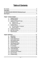
Table of Contents Box Contents ...6 OptionalItems...6 GA-945GCM-S2L/GA-945GCM-S2C Motherboard Layout 7 Block Diagram...8 Chapter 1 Hardware Installation 9 1-1 Installation Precautions 9 1-2 Product Specifications 10 1-3 Installing the CPU and CPU Cooler 13 1-3-1 Installing the CPU 13 1-3-2 Installing the CPU Cooler 15 1-4 Installing the Memory 16 1-4-1 Dual Channel Memory Configuration 16 1-4-2 Installing a Memory 17 1-5 Installing an Expansion Card 18 1-6 Back Panel Connectors...
Table of Contents Box Contents ...6 OptionalItems...6 GA-945GCM-S2L/GA-945GCM-S2C Motherboard Layout 7 Block Diagram...8 Chapter 1 Hardware Installation 9 1-1 Installation Precautions 9 1-2 Product Specifications 10 1-3 Installing the CPU and CPU Cooler 13 1-3-1 Installing the CPU 13 1-3-2 Installing the CPU Cooler 15 1-4 Installing the Memory 16 1-4-1 Dual Channel Memory Configuration 16 1-4-2 Installing a Memory 17 1-5 Installing an Expansion Card 18 1-6 Back Panel Connectors...
Manual
Page 8
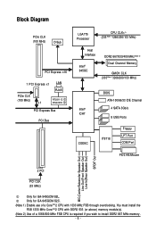
... (100 MHz) D-Sub PCI Express x16 1 PCI Express x1 LAN RJ45 PCIe CLK (100 MHz) x1 RTL8111C RTL8101E PCI Express Bus PCI Bus LGA775 Processor CPU CLK+/(333(Note 1)/266/200/133 MHz) Host Interface Intel® 945GC DDR2 667/533/400 MHz(Note 2) Dual Channel Memory GMCH CLK (333(Note.../Mouse MIC(Center/Subwoofer Speaker Out) Line-Out(Front Speaker Out) Line-In(Rear Speaker Out) SPDIF Out 2 PCI PCI CLK (33 MHz) Only for GA-945GCM-S2C. (Note 1) Enable use of a 1066/800 MHz FSB CPU is required if you wish to install DDR2 667 MHz memory. - 8 - Only for GA-945GCM-S2L.
... (100 MHz) D-Sub PCI Express x16 1 PCI Express x1 LAN RJ45 PCIe CLK (100 MHz) x1 RTL8111C RTL8101E PCI Express Bus PCI Bus LGA775 Processor CPU CLK+/(333(Note 1)/266/200/133 MHz) Host Interface Intel® 945GC DDR2 667/533/400 MHz(Note 2) Dual Channel Memory GMCH CLK (333(Note.../Mouse MIC(Center/Subwoofer Speaker Out) Line-Out(Front Speaker Out) Line-In(Rear Speaker Out) SPDIF Out 2 PCI PCI CLK (33 MHz) Only for GA-945GCM-S2C. (Note 1) Enable use of a 1066/800 MHz FSB CPU is required if you wish to install DDR2 667 MHz memory. - 8 - Only for GA-945GCM-S2L.

Manual
Page 9
.... • Prior to installing the motherboard, please have a problem related to wear an electrostatic discharge (ESD) wrist strap when handling electronic components such as a motherboard, CPU or memory. Prior to installation, carefully read the user's manual and follow these procedures: • Prior to installation, do not allow screws to come in...
.... • Prior to installing the motherboard, please have a problem related to wear an electrostatic discharge (ESD) wrist strap when handling electronic components such as a motherboard, CPU or memory. Prior to installation, carefully read the user's manual and follow these procedures: • Prior to installation, do not allow screws to come in...
Manual
Page 10
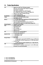
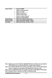
GA-945GCM-S2L/S2C Motherboard - 10 - 1-2 Product Specifications CPU Front Side Bus Chipset Memory Onboard Graphics Audio LAN Expansion Slots Storage Interface USB Š Support for an Intel® CoreTM 2 Extreme processor/ Intel® ... up to 4 GB of system memory (Note 2) Š Dual channel memory architecture Š Support for DDR2 667/533/400 MHz memory modules (Note 3) (Go to GIGABYTE's website for the latest memory support list.) Š Integrated in the North Bridge Š Realtek ALC662 codec Š High Definition Audio Š 2/4/5.1-channel Š Support...
GA-945GCM-S2L/S2C Motherboard - 10 - 1-2 Product Specifications CPU Front Side Bus Chipset Memory Onboard Graphics Audio LAN Expansion Slots Storage Interface USB Š Support for an Intel® CoreTM 2 Extreme processor/ Intel® ... up to 4 GB of system memory (Note 2) Š Dual channel memory architecture Š Support for DDR2 667/533/400 MHz memory modules (Note 3) (Go to GIGABYTE's website for the latest memory support list.) Š Integrated in the North Bridge Š Realtek ALC662 codec Š High Definition Audio Š 2/4/5.1-channel Š Support...

Manual
Page 11
...Š 1 x 4-pin ATX 12V power connector Š 1 x floppy disk drive connector Š 1 x IDE connector Š 4 x SATA 3Gb/s connectors Š 1 x CPU fan header Š 1 x system fan header Š 1 x front panel header Š 1 x front panel audio header Š 1 x CD In connector Š 1 x... Š iTE IT8718 chip Hardware Monitor Š System voltage detection Š CPU temperature detection Š CPU/System fan speed detection Š CPU overheating warning Š CPU/System fan fail warning Š CPU fan speed control BIOS Š 1 x 4 Mbit flash Š Use ...
...Š 1 x 4-pin ATX 12V power connector Š 1 x floppy disk drive connector Š 1 x IDE connector Š 4 x SATA 3Gb/s connectors Š 1 x CPU fan header Š 1 x system fan header Š 1 x front panel header Š 1 x front panel audio header Š 1 x CD In connector Š 1 x... Š iTE IT8718 chip Hardware Monitor Š System voltage detection Š CPU temperature detection Š CPU/System fan speed detection Š CPU overheating warning Š CPU/System fan fail warning Š CPU fan speed control BIOS Š 1 x 4 Mbit flash Š Use ...
Manual
Page 12
...Micro ATX form factor; 24.4cm x 19.3cm (Note 1) Enable use of a 1066/800 MHz FSB CPU is installed, the actual memory size displayed will be less than 4 GB. (Note 3) Use of a CoreTM 2 CPU with DDR2 533 (or above) memory module(s). (Note 2) Due to Windows Vista/XP 32-bit operating ...system limitation, when more than 4 GB of physical memory is required if you wish to install DDR2 667 MHz memory. (Note 4) Available functions in Easytune may differ by motherboard model. GA-945GCM-S2L/S2C ...
...Micro ATX form factor; 24.4cm x 19.3cm (Note 1) Enable use of a 1066/800 MHz FSB CPU is installed, the actual memory size displayed will be less than 4 GB. (Note 3) Use of a CoreTM 2 CPU with DDR2 533 (or above) memory module(s). (Note 2) Due to Windows Vista/XP 32-bit operating ...system limitation, when more than 4 GB of physical memory is required if you wish to install DDR2 667 MHz memory. (Note 4) Available functions in Easytune may differ by motherboard model. GA-945GCM-S2L/S2C ...

Manual
Page 13
... Hyper-Threading Technology) • An Intel® CPU that supports HT Technology • A chipset that supports HT Technology • An operating system that the motherboard supports the CPU. (Go to GIGABYTE's website for the latest CPU support list.) • Always turn on enabling the... HT Technology.) 1-3-1 Installing the CPU A. Locate the alignment keys on the motherboard CPU socket and the notches on the CPU Hardware Installation It is ...
... Hyper-Threading Technology) • An Intel® CPU that supports HT Technology • A chipset that supports HT Technology • An operating system that the motherboard supports the CPU. (Go to GIGABYTE's website for the latest CPU support list.) • Always turn on enabling the... HT Technology.) 1-3-1 Installing the CPU A. Locate the alignment keys on the motherboard CPU socket and the notches on the CPU Hardware Installation It is ...

Manual
Page 14
... lever back into the motherboard CPU socket. Align the CPU pin one marking (triangle) with the pin one corner of the CPU socket (or you may align the CPU notches with your thumb and index fingers. CPU Socket Lever Step 1: Completely raise the CPU socket lever. GA-945GCM-S2L/S2C Motherboard - 14 - B. Before installing the CPU, make sure to correctly...
... lever back into the motherboard CPU socket. Align the CPU pin one marking (triangle) with the pin one corner of the CPU socket (or you may align the CPU notches with your thumb and index fingers. CPU Socket Lever Step 1: Completely raise the CPU socket lever. GA-945GCM-S2L/S2C Motherboard - 14 - B. Before installing the CPU, make sure to correctly...

Manual
Page 15
...hear a "click" when pushing down on the push pins diagonally. Use extreme care when removing the CPU cooler because the thermal grease/tape between the CPU cooler and CPU may damage the CPU. - 15 - Push down each push pin. If the push pin is inserted as the example ...Hardware Installation Step 6: Finally, attach the power connector of the installed CPU. Inadequately removing the CPU cooler may adhere to the CPU. 1-3-2 Installing the CPU Cooler Follow the steps below to correctly install the CPU cooler on the motherboard. (The following procedure uses Intel® boxed ...
...hear a "click" when pushing down on the push pins diagonally. Use extreme care when removing the CPU cooler because the thermal grease/tape between the CPU cooler and CPU may damage the CPU. - 15 - Push down each push pin. If the push pin is inserted as the example ...Hardware Installation Step 6: Finally, attach the power connector of the installed CPU. Inadequately removing the CPU cooler may adhere to the CPU. 1-3-2 Installing the CPU Cooler Follow the steps below to correctly install the CPU cooler on the motherboard. (The following procedure uses Intel® boxed ...

Manual
Page 22
... or unbootable system. • The main power connector is turned off and all the components on the motherboard. Connect the power supply cable to the CPU. Do not insert the power supply cable into pins under the protective cover when using a 2x12 power supply, remove the protective cover from the main... Definition 3.3V -12V GND PS_ON(soft On/Off) GND GND GND -5V +5V +5V +5V (Only for 2x12-pinATX) GND (Only for 2x12-pin ATX) GA-945GCM-S2L/S2C Motherboard - 22 -
... or unbootable system. • The main power connector is turned off and all the components on the motherboard. Connect the power supply cable to the CPU. Do not insert the power supply cable into pins under the protective cover when using a 2x12 power supply, remove the protective cover from the main... Definition 3.3V -12V GND PS_ON(soft On/Off) GND GND GND -5V +5V +5V +5V (Only for 2x12-pinATX) GND (Only for 2x12-pin ATX) GA-945GCM-S2L/S2C Motherboard - 22 -

Manual
Page 23
... The pin 1 of different color. 33 1 34 2 - 23 - Hardware Installation 3/4) CPU_FAN/SYS_FAN (Fan Headers) The motherboard has a 4-pin CPU fan header (CPU_FAN) and a 3-pin system fan header (SYS_FAN). Overheating may result in the correct orientation. The types of the connector and the floppy...to locate pin 1 of floppy disk drives supported are not configuration jumper blocks. When connecting a fan cable, be sure to prevent your CPU and system from overheating. Do not place a jumper cap on the headers. 5) FDD (Floppy Disk Drive Connector) This connector is ...
... The pin 1 of different color. 33 1 34 2 - 23 - Hardware Installation 3/4) CPU_FAN/SYS_FAN (Fan Headers) The motherboard has a 4-pin CPU fan header (CPU_FAN) and a 3-pin system fan header (SYS_FAN). Overheating may result in the correct orientation. The types of the connector and the floppy...to locate pin 1 of floppy disk drives supported are not configuration jumper blocks. When connecting a fan cable, be sure to prevent your CPU and system from overheating. Do not place a jumper cap on the headers. 5) FDD (Floppy Disk Drive Connector) This connector is ...

Manual
Page 34
...User Password Change, set , or disable password. Pressing to the confirmation message will exit BIOS Setup. (Pressing can also carry out this task.) GA-945GCM-S2L/S2C Motherboard - 34 - A supervisor password allows you to restrict access to the system and BIOS Setup. „ Standard CMOS Features Use this...stop the system boot, etc. „ Advanced BIOS Features Use this menu to configure the device boot order, advanced features available on the CPU, and the primary display adapter. „ Integrated Peripherals Use this menu to configure all peripheral devices, such as IDE, SATA, USB,...
...User Password Change, set , or disable password. Pressing to the confirmation message will exit BIOS Setup. (Pressing can also carry out this task.) GA-945GCM-S2L/S2C Motherboard - 34 - A supervisor password allows you to restrict access to the system and BIOS Setup. „ Standard CMOS Features Use this...stop the system boot, etc. „ Advanced BIOS Features Use this menu to configure the device boot order, advanced features available on the CPU, and the primary display adapter. „ Integrated Peripherals Use this menu to configure all peripheral devices, such as IDE, SATA, USB,...

Manual
Page 37
...A password is required every time the system boots, or only when you install a CPU that support multi-processors mode. (Default: Enabled) (Note) This item is installed. (Default: Disabled) CPU Hyper-Threading (Note) Enables or disables Intel® Hyper-Threading Technology. HDD S.M.A.R.T.... the up or down arrow key to select a device and press to 3 (Note) No-Execute Memory Protect (Note) CPU Enhanced Halt (C1E) (Note) CPU Thermal Monitor 2(TM2) (Note) CPU EIST Function (Note) Virtualization Technology (Note) [Disabled] [Enabled] [Disabled] [Enabled] [Enabled] [Enabled] [Enabled] ...
...A password is required every time the system boots, or only when you install a CPU that support multi-processors mode. (Default: Enabled) (Note) This item is installed. (Default: Disabled) CPU Hyper-Threading (Note) Enables or disables Intel® Hyper-Threading Technology. HDD S.M.A.R.T.... the up or down arrow key to select a device and press to 3 (Note) No-Execute Memory Protect (Note) CPU Enhanced Halt (C1E) (Note) CPU Thermal Monitor 2(TM2) (Note) CPU EIST Function (Note) Virtualization Technology (Note) [Disabled] [Enabled] [Disabled] [Enabled] [Enabled] [Enabled] [Enabled] ...

Manual
Page 38
... system halt state to run multiple operating systems and applications in system halt state. GA-945GCM-S2L/S2C Motherboard - 38 - Limit CPUID Max. to 3 (Note) Allows you install a CPU that supports this memory for the onboard graphics controller. When enabled, the CPU core frequency and voltage will allow a platform to decrease power consumption. (Default: Enabled...
... system halt state to run multiple operating systems and applications in system halt state. GA-945GCM-S2L/S2C Motherboard - 38 - Limit CPUID Max. to 3 (Note) Allows you install a CPU that supports this memory for the onboard graphics controller. When enabled, the CPU core frequency and voltage will allow a platform to decrease power consumption. (Default: Enabled...

Manual
Page 46
...your system. CPU Warning Temperature Sets the warning threshold for CPU temperature. Enabled clears the record of previous chassis intrusion status. CPU/SYSTEM FAN Fail Warning Allows the system to emit warning sound if the CPU/system fan is removed, this occurs. (Default: Disabled) GA-945GCM-S2L/S2C Motherboard -...Health Status Reset Case Open Status Case Opened Vcore DDR18V +3.3V +12V Current CPU Temperature Current CPU FAN Speed Current SYSTEM FAN Speed CPU Warning Temperature CPU FAN Fail Warning SYSTEM FAN Fail Warning CPU Smart FAN Control [Disabled] No OK OK OK OK 47oC 3375 RPM 0...
...your system. CPU Warning Temperature Sets the warning threshold for CPU temperature. Enabled clears the record of previous chassis intrusion status. CPU/SYSTEM FAN Fail Warning Allows the system to emit warning sound if the CPU/system fan is removed, this occurs. (Default: Disabled) GA-945GCM-S2L/S2C Motherboard -...Health Status Reset Case Open Status Case Opened Vcore DDR18V +3.3V +12V Current CPU Temperature Current CPU FAN Speed Current SYSTEM FAN Speed CPU Warning Temperature CPU FAN Fail Warning SYSTEM FAN Fail Warning CPU Smart FAN Control [Disabled] No OK OK OK OK 47oC 3375 RPM 0...

Manual
Page 47
If disabled, CPU fan runs at different speed according to run at full speed. (Default: Enabled) - 47 - BIOS Setup Enabled allows the CPU fan to the CPU temperature. CPU Smart FAN Control Enables or disables the CPU fan speed control function. You can adjust the fan speed with EasyTune based on system requirements.
If disabled, CPU fan runs at different speed according to run at full speed. (Default: Enabled) - 47 - BIOS Setup Enabled allows the CPU fan to the CPU temperature. CPU Smart FAN Control Enables or disables the CPU fan speed control function. You can adjust the fan speed with EasyTune based on system requirements.

Manual
Page 48
.... You must install the FSB 1333 MHz CoreTM 2 CPU with unlocked clock ratio is for advanced users only and we recommend you want to enable the use of a FSB 1333 CoreTM 2 processor. GA-945GCM-S2L/S2C Motherboard - 48 - 2-9 Frequency/Voltage Control CMOS... Setup Utility-Copyright (C) 1984-2007 Award Software Frequency/Voltage Control CPU Clock Ratio (Note) O.C FSB1333 Core. 2 CPU CPU Host Clock Control x CPU Host Frequency(Mhz) PCI Express Frequency (Mhz) ...
.... You must install the FSB 1333 MHz CoreTM 2 CPU with unlocked clock ratio is for advanced users only and we recommend you want to enable the use of a FSB 1333 CoreTM 2 processor. GA-945GCM-S2L/S2C Motherboard - 48 - 2-9 Frequency/Voltage Control CMOS... Setup Utility-Copyright (C) 1984-2007 Award Software Frequency/Voltage Control CPU Clock Ratio (Note) O.C FSB1333 Core. 2 CPU CPU Host Clock Control x CPU Host Frequency(Mhz) PCI Express Frequency (Mhz) ...

Manual
Page 49
...1V ~ +0.4V Increases memory voltage by 0.1V to set in accordance with the CPU specifications. This item is configurable only if the CPU Host Clock Control option is highly recommended that the CPU frequency be set memory voltage. Important It is enabled. Note: Increasing memory voltage...System Memory Multiplier Allows you to manually set the Front Side Bus voltage. Normal CPU Vcore Displays the normal operating voltage of the CPU. DIMM OverVoltage Control Allows you to manually set the CPU voltage. BIOS Setup PCI Express Frequency (Mhz) Allows you to 0.3V at 0....
...1V ~ +0.4V Increases memory voltage by 0.1V to set in accordance with the CPU specifications. This item is configurable only if the CPU Host Clock Control option is highly recommended that the CPU frequency be set memory voltage. Important It is enabled. Note: Increasing memory voltage...System Memory Multiplier Allows you to manually set the Front Side Bus voltage. Normal CPU Vcore Displays the normal operating voltage of the CPU. DIMM OverVoltage Control Allows you to manually set the CPU voltage. BIOS Setup PCI Express Frequency (Mhz) Allows you to 0.3V at 0....

Manual
Page 67
... the Smart-Fan setting page Enters the PC Health setting page Confirmation and Execution button Toggles between Easy and Advance Mode Displays panel of CPU frequency Shows the information of the current function Visits GIGABYTE website Displays EasyTuneTM 5 help screen Quits or minimizes EasyTuneTM 5 Incorrectly doing overclock/overvoltage may provide optimizations for...
... the Smart-Fan setting page Enters the PC Health setting page Confirmation and Execution button Toggles between Easy and Advance Mode Displays panel of CPU frequency Shows the information of the current function Visits GIGABYTE website Displays EasyTuneTM 5 help screen Quits or minimizes EasyTuneTM 5 Incorrectly doing overclock/overvoltage may provide optimizations for...

Manual
Page 78
... power. Turn on the memory slot. The problem is attached to the CPU_FAN header properly? Connect the CPU cooler power cable to enter BIOS Setup. A (Continued...) GA-945GCM-S2L/S2C Motherboard - 78 - No Check if the CPU cooler is verified and solved. Yes Isolate the short circuit. No Correctly insert the memory into the memory...
... power. Turn on the memory slot. The problem is attached to the CPU_FAN header properly? Connect the CPU cooler power cable to enter BIOS Setup. A (Continued...) GA-945GCM-S2L/S2C Motherboard - 78 - No Check if the CPU cooler is verified and solved. Yes Isolate the short circuit. No Correctly insert the memory into the memory...


