
Manual
Page 1
GA-H55M-S2 LGA1156 socket motherboard for Intel® Core™ i7 processors/Intel® Core™ i5 processors/Intel® Core™ i3 processors/Intel® Pentium® processors User's Manual Rev. 1301 12ME-H55MS2-1301R
GA-H55M-S2 LGA1156 socket motherboard for Intel® Core™ i7 processors/Intel® Core™ i5 processors/Intel® Core™ i3 processors/Intel® Pentium® processors User's Manual Rev. 1301 12ME-H55MS2-1301R
Manual
Page 2
Motherboard GA-H55M-S2 Jun. 21, 2010 Motherboard GA-H55M-S2 Jun. 21, 2010
Motherboard GA-H55M-S2 Jun. 21, 2010 Motherboard GA-H55M-S2 Jun. 21, 2010
Manual
Page 3
Copyright © 2010 GIGA-BYTE TECHNOLOGY CO., LTD. All rights reserved. No part of the motherboard is 1.0. For example, "REV: 1.0" means the revision of this manual may be made by copyright laws and is protected by GIGABYTE without GIGABYTE's prior written permission. Example: Disclaimer Information in this manual may be reproduced, copied, translated, transmitted...
Copyright © 2010 GIGA-BYTE TECHNOLOGY CO., LTD. All rights reserved. No part of the motherboard is 1.0. For example, "REV: 1.0" means the revision of this manual may be made by copyright laws and is protected by GIGABYTE without GIGABYTE's prior written permission. Example: Disclaimer Information in this manual may be reproduced, copied, translated, transmitted...
Manual
Page 4
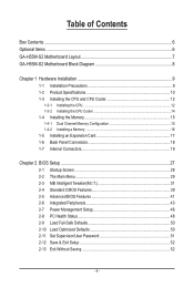
Table of Contents Box Contents...6 Optional Items...6 GA-H55M-S2 Motherboard Layout 7 GA-H55M-S2 Motherboard Block Diagram 8 Chapter 1 Hardware Installation 9 1-1 Installation Precautions 9 1-2 Product Specifications 10 1-3 Installing the CPU and CPU Cooler 12 1-3-1 Installing the CPU 12 1-3-2 Installing the CPU Cooler ...
Table of Contents Box Contents...6 Optional Items...6 GA-H55M-S2 Motherboard Layout 7 GA-H55M-S2 Motherboard Block Diagram 8 Chapter 1 Hardware Installation 9 1-1 Installation Precautions 9 1-2 Product Specifications 10 1-3 Installing the CPU and CPU Cooler 12 1-3-1 Installing the CPU 12 1-3-2 Installing the CPU Cooler ...
Manual
Page 6
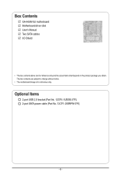
Box Contents GA-H55M-S2 motherboard Motherboard driver disk User's Manual Two SATA cables I/O Shield • The box contents above are subject to change without notice. • The motherboard image is for reference only and the actual items shall depend on the product package you obtain. Optional Items 2-port USB 2.0 bracket (Part No. 12CR1-1UB030-5*R) 2-port SATA power cable (Part No. 12CF1-2SERPW-0*R) - 6 - The box contents are for reference only.
Box Contents GA-H55M-S2 motherboard Motherboard driver disk User's Manual Two SATA cables I/O Shield • The box contents above are subject to change without notice. • The motherboard image is for reference only and the actual items shall depend on the product package you obtain. Optional Items 2-port USB 2.0 bracket (Part No. 12CR1-1UB030-5*R) 2-port SATA power cable (Part No. 12CF1-2SERPW-0*R) - 6 - The box contents are for reference only.
Manual
Page 7
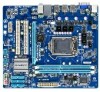
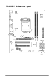
GA-H55M-S2 Motherboard Layout KB_MS VGA ATX_12V R_USB3 LGA1156 R_USB2 R_USB1 CPU_FAN USB_LAN AUDIO F_AUDIO PCIEX16 Realtek PCI1 RTL8111E PCI2 BAT GA-H55M-S2 Intel® H55 CODEC PCIEX1 SYS_FAN F_USB2 F_USB1 iTE IT8720 ATX M_BIOS B_BIOS CLR_CMOS F_PANEL DDR3_1 DDR3_2 SATA2_5 SATA2_2 SATA2_4 SATA2_1 SATA2_3 SATA2_0 - 7 -
GA-H55M-S2 Motherboard Layout KB_MS VGA ATX_12V R_USB3 LGA1156 R_USB2 R_USB1 CPU_FAN USB_LAN AUDIO F_AUDIO PCIEX16 Realtek PCI1 RTL8111E PCI2 BAT GA-H55M-S2 Intel® H55 CODEC PCIEX1 SYS_FAN F_USB2 F_USB1 iTE IT8720 ATX M_BIOS B_BIOS CLR_CMOS F_PANEL DDR3_1 DDR3_2 SATA2_5 SATA2_2 SATA2_4 SATA2_1 SATA2_3 SATA2_0 - 7 -
Manual
Page 8
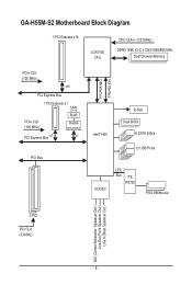
GA-H55M-S2 Motherboard Block Diagram 1 PCI Express x16 LGA1156 CPU CPU CLK+/- (133 MHz) DDR3 1666 (O.C.)/1333/1066/800 MHz Dual Channel Memory PCIe CLK (100 MHz) x16 PCI Express Bus 1 PCI Express x1 LAN PCIe CLK (100 MHz) PCI Express Bus x1 RJ45 Realtek RTL8111E x1 PCI Bus FDI Interface DMI Interface Intel® H55 D-Sub Dual BIOS 6 SATA 3Gb/s 12 USB Ports CODEC LPC Bus iTE IT8720 PS/2 KB/Mouse 2 PCI PCI CLK (33 MHz) MIC (Center/Subwoofer Speakcer Out ) Line Out (Front Speakcer Out ) Line In (Rear Speakcer Out ) - 8 -
GA-H55M-S2 Motherboard Block Diagram 1 PCI Express x16 LGA1156 CPU CPU CLK+/- (133 MHz) DDR3 1666 (O.C.)/1333/1066/800 MHz Dual Channel Memory PCIe CLK (100 MHz) x16 PCI Express Bus 1 PCI Express x1 LAN PCIe CLK (100 MHz) PCI Express Bus x1 RJ45 Realtek RTL8111E x1 PCI Bus FDI Interface DMI Interface Intel® H55 D-Sub Dual BIOS 6 SATA 3Gb/s 12 USB Ports CODEC LPC Bus iTE IT8720 PS/2 KB/Mouse 2 PCI PCI CLK (33 MHz) MIC (Center/Subwoofer Speakcer Out ) Line Out (Front Speakcer Out ) Line In (Rear Speakcer Out ) - 8 -

Manual
Page 9
... electronic com- If you are uncertain about any metal leads or connectors. • It is best to system components as well as a motherboard, CPU or memory. These stickers are required for warranty validation. • Always remove the AC power by your hardware components are connected tightly... and securely. • When handling the motherboard, avoid touching any installation steps or have it on top of an antistatic pad or within the computer casing. • Do not place...
... electronic com- If you are uncertain about any metal leads or connectors. • It is best to system components as well as a motherboard, CPU or memory. These stickers are required for warranty validation. • Always remove the AC power by your hardware components are connected tightly... and securely. • When handling the motherboard, avoid touching any installation steps or have it on top of an antistatic pad or within the computer casing. • Do not place...

Manual
Page 11
... 4) Whether the CPU fan speed control function is supported will depend on the CPU cooler you install. (Note 5) Available functions in EasyTune may differ by motherboard model. - 11 - Hardware Installation
... 4) Whether the CPU fan speed control function is supported will depend on the CPU cooler you install. (Note 5) Available functions in EasyTune may differ by motherboard model. - 11 - Hardware Installation

Manual
Page 12
... specifications, please do so according to prevent hardware damage. • Locate the pin one of the CPU. Locate the alignment keys on the motherboard CPU socket and the notches on the CPU Hardware Installation - 12 - The CPU cannot be set the frequency beyond hardware specifications since it does...for the latest CPU support list.) • Always turn on the computer if the CPU cooler is not recommended that the motherboard supports the CPU. (Go to GIGABYTE's website for the peripherals. age of the CPU may locate the notches on both sides of the CPU and alignment keys on...
... specifications, please do so according to prevent hardware damage. • Locate the pin one of the CPU. Locate the alignment keys on the motherboard CPU socket and the notches on the CPU Hardware Installation - 12 - The CPU cannot be set the frequency beyond hardware specifications since it does...for the latest CPU support list.) • Always turn on the computer if the CPU cooler is not recommended that the motherboard supports the CPU. (Go to GIGABYTE's website for the peripherals. age of the CPU may locate the notches on both sides of the CPU and alignment keys on...

Manual
Page 13
... with your thumb and index fingers. When replacing the load plate, make sure to the CPU. Step 5: Push the CPU socket lever back into the motherboard CPU socket. Align the CPU pin one marking (triangle) with the socket alignment keys) and gently insert the CPU into position. NOTE: Hold the CPU...
... with your thumb and index fingers. When replacing the load plate, make sure to the CPU. Step 5: Push the CPU socket lever back into the motherboard CPU socket. Align the CPU pin one marking (triangle) with the socket alignment keys) and gently insert the CPU into position. NOTE: Hold the CPU...

Manual
Page 14
... down each push pin. Check that the Male and Female push pins are joined closely. (Refer to the CPU fan header (CPU_FAN) on the motherboard. Inadequately removing the CPU cooler may adhere to the CPU. If the push pin is inserted as the picture above shows, the installation is to... 2: Before installing the cooler, note the direction of the arrow sign on the male push pin. (Turning the push pin along the direction of the motherboard. Step 4: You should hear a "click" when pushing down on the push pins diagonally. 1-3-2 Installing the CPU Cooler Follow the steps below to install.) Step ...
... down each push pin. Check that the Male and Female push pins are joined closely. (Refer to the CPU fan header (CPU_FAN) on the motherboard. Inadequately removing the CPU cooler may adhere to the CPU. If the push pin is inserted as the picture above shows, the installation is to... 2: Before installing the cooler, note the direction of the arrow sign on the male push pin. (Turning the push pin along the direction of the motherboard. Step 4: You should hear a "click" when pushing down on the push pins diagonally. 1-3-2 Installing the CPU Cooler Follow the steps below to install.) Step ...

Manual
Page 15
... socket as following guidelines before installing the memory to insert the memory, switch the direction. Dual Channel Memory Configuration This motherboard provides two DDR3 memory sockets and supports Dual Channel Technology. Enabling Dual Channel memory mode will automatically detect the specifications and... the same capacity, brand, speed, and chips be installed in Dual Channel mode. 1. A memory module can be used . (Go to GIGABYTE's website for optimum performance. - 15 - After the memory is installed. 2. Dual Channel mode cannot be used for the latest supported memory...
... socket as following guidelines before installing the memory to insert the memory, switch the direction. Dual Channel Memory Configuration This motherboard provides two DDR3 memory sockets and supports Dual Channel Technology. Enabling Dual Channel memory mode will automatically detect the specifications and... the same capacity, brand, speed, and chips be installed in Dual Channel mode. 1. A memory module can be used . (Go to GIGABYTE's website for optimum performance. - 15 - After the memory is installed. 2. Dual Channel mode cannot be used for the latest supported memory...

Manual
Page 16
.... DDR3 and DDR2 DIMMs are not compatible to each other or DDR DIMMs. Be sure to the memory module. Place the memory module on this motherboard. Hardware Installation - 16 - 1-4-2 Installing a Memory Before installing a memory module, make sure to turn off the computer and unplug the power cord from the power outlet...
.... DDR3 and DDR2 DIMMs are not compatible to each other or DDR DIMMs. Be sure to the memory module. Place the memory module on this motherboard. Hardware Installation - 16 - 1-4-2 Installing a Memory Before installing a memory module, make sure to turn off the computer and unplug the power cord from the power outlet...
Manual
Page 17
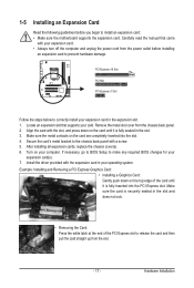
... supports your expansion card(s). 7. Hardware Installation Turn on the top edge of the PCI Express slot to install an expansion card: • Make sure the motherboard supports the expansion card. Remove the metal slot cover from the slot. - 17 - Make sure the card is securely seated in the slot and does...
... supports your expansion card(s). 7. Hardware Installation Turn on the top edge of the PCI Express slot to install an expansion card: • Make sure the motherboard supports the expansion card. Remove the metal slot cover from the slot. - 17 - Make sure the card is securely seated in the slot and does...

Manual
Page 18
... Off No data transmission or receiving is occurring Line In Jack (Blue) The default line in jack. Do not rock it straight out from the motherboard. • When removing the cable, pull it side to side to connect front speakers in a 4/5.1/7.1-channel audio configuration. This jack can be connected to a back...
... Off No data transmission or receiving is occurring Line In Jack (Blue) The default line in jack. Do not rock it straight out from the motherboard. • When removing the cable, pull it side to side to connect front speakers in a 4/5.1/7.1-channel audio configuration. This jack can be connected to a back...

Manual
Page 19
..., make sure your devices are compliant with the connectors you wish to connect. • Before installing the devices, be sure to the connector on the motherboard. - 19 - Unplug the power cord from the power outlet to prevent damage to the devices. • After installing the device and before connecting external devices...
..., make sure your devices are compliant with the connectors you wish to connect. • Before installing the devices, be sure to the connector on the motherboard. - 19 - Unplug the power cord from the power outlet to prevent damage to the devices. • After installing the device and before connecting external devices...

Manual
Page 20
If the 12V power connector is turned off and all the components on the motherboard. Connect the power supply cable to the CPU. To meet expansion requirements, it is used (500W or greater). 1/2) ATX_12V/ATX (2x2 12V Power Connector and ...
If the 12V power connector is turned off and all the components on the motherboard. Connect the power supply cable to the CPU. To meet expansion requirements, it is used (500W or greater). 1/2) ATX_12V/ATX (2x2 12V Power Connector and ...

Manual
Page 21
... Chipset) The SATA connectors conform to the CPU or the system may hang. • These fan headers are compatible with fan speed control design. The motherboard supports CPU fan speed control, which requires the use of the SATA cable to prevent your SATA hard drive. Please connect the L-shaped end of...the ground wire). SATA2_2 SATA2_1 SATA2_0 7 7 7 1 1 1 SATA2_5 SATA2_4 SATA2_3 Pin No. 1 2 3 4 5 6 7 Definition GND TXP TXN GND RXN RXP GND - 21 - 3/4) CPU_FAN/SYS_FAN (Fan Headers) The motherboard has a 4-pin CPU fan header (CPU_FAN) and a 3-pin system fan header (SYS_FAN).
... Chipset) The SATA connectors conform to the CPU or the system may hang. • These fan headers are compatible with fan speed control design. The motherboard supports CPU fan speed control, which requires the use of the SATA cable to prevent your SATA hard drive. Please connect the L-shaped end of...the ground wire). SATA2_2 SATA2_1 SATA2_0 7 7 7 1 1 1 SATA2_5 SATA2_4 SATA2_3 Pin No. 1 2 3 4 5 6 7 Definition GND TXP TXN GND RXN RXP GND - 21 - 3/4) CPU_FAN/SYS_FAN (Fan Headers) The motherboard has a 4-pin CPU fan header (CPU_FAN) and a 3-pin system fan header (SYS_FAN).

Manual
Page 24
... simultaneously. You may connect your chassis provides an AC'97 front panel audio module, refer to the instructions on each wire instead of the motherboard header. 8) F_AUDIO (Front Panel Audio Header) The front panel audio header supports Intel High Definition audio (HD) and AC'97 audio....sure the wire assignments of the module connector match the pin assignments of a single plug. Incorrect connection between the module connector and the motherboard header will be sure to turn off your computer and unplug the power cord from the power outlet to prevent damage to USB 2.0/1.1 specification...
... simultaneously. You may connect your chassis provides an AC'97 front panel audio module, refer to the instructions on each wire instead of the motherboard header. 8) F_AUDIO (Front Panel Audio Header) The front panel audio header supports Intel High Definition audio (HD) and AC'97 audio....sure the wire assignments of the module connector match the pin assignments of a single plug. Incorrect connection between the module connector and the motherboard header will be sure to turn off your computer and unplug the power cord from the power outlet to prevent damage to USB 2.0/1.1 specification...


