Universal H Series Troubleshooting Guide
Page 4
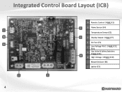
Integrated Control Board Layout (ICB) C B A J 4 D I E A Remote Control: 24VAC (E1) F B Flame Sensor (E4) C Temperature Sensor (E2) G D Display Output: 24VAC (E7) E 3A Fuse (F1) F Low Voltage R & C: 24VAC (E12, E13) G Gas Valve & Safety Switches: 24VAC (E11) H H High Voltage: 120VAC (E10) I Blower/Inducer (E6) J Ignitor (E3)
Integrated Control Board Layout (ICB) C B A J 4 D I E A Remote Control: 24VAC (E1) F B Flame Sensor (E4) C Temperature Sensor (E2) G D Display Output: 24VAC (E7) E 3A Fuse (F1) F Low Voltage R & C: 24VAC (E12, E13) G Gas Valve & Safety Switches: 24VAC (E11) H H High Voltage: 120VAC (E10) I Blower/Inducer (E6) J Ignitor (E3)

Universal H Series Troubleshooting Guide
Page 7
... closed blower vacuum switch. 4. NOTE: If during call for more details outlining failure to light operations. 7 Gas valve opens and monitors flame sense. The control checks for open blower vacuum switch 2. When the water temp is 1º below the set temp is de-energized at...the next page for heat. If the flame is extinguished. 6. At proper ignitor temp, a 4 second trial begins. UHS Sequence of 4 sec trial. The gas valve is de-energized, and the flame is sensed, The blower vacuum switch, control loop, temp sensor & flame sensor are constantly monitored during step four, the...
... closed blower vacuum switch. 4. NOTE: If during call for more details outlining failure to light operations. 7 Gas valve opens and monitors flame sense. The control checks for open blower vacuum switch 2. When the water temp is 1º below the set temp is de-energized at...the next page for heat. If the flame is extinguished. 6. At proper ignitor temp, a 4 second trial begins. UHS Sequence of 4 sec trial. The gas valve is de-energized, and the flame is sensed, The blower vacuum switch, control loop, temp sensor & flame sensor are constantly monitored during step four, the...

Universal H Series Troubleshooting Guide
Page 19
...Vacuum Switch closed Blower Vacuum Switch open Bad board or secondary high voltage fault Communication Error Between Control Module and Display Interface Assembly Bad board Flame present with Gas Valve not energized. Maximum return water temperature exceeded and / or rapid water temperature rise. Ignition Failure Ignitor Circuit Open ...Water Pressure Switch, Vent Pressure Switch, or Temperature Limit Switch Fault Voltage polarity reversed, low voltage detected Keypad failure Temperature Sensor (thermistor) input failure 19 Troubleshooting Steps for the UHS Heater.
...Vacuum Switch closed Blower Vacuum Switch open Bad board or secondary high voltage fault Communication Error Between Control Module and Display Interface Assembly Bad board Flame present with Gas Valve not energized. Maximum return water temperature exceeded and / or rapid water temperature rise. Ignition Failure Ignitor Circuit Open ...Water Pressure Switch, Vent Pressure Switch, or Temperature Limit Switch Fault Voltage polarity reversed, low voltage detected Keypad failure Temperature Sensor (thermistor) input failure 19 Troubleshooting Steps for the UHS Heater.

Universal H Series Troubleshooting Guide
Page 20
... Control Panel 350 FDXLBCP1400 Kit-Bezel Control Panel 400 FDXLBCP1500 Kit-Bezel Control Panel 500 20 IDXLFLS1930 IDXLFLS1930 Flame Sensor (3" & 5") FDXLFSK1930 FDXLFSK1930 Fuse Kit FDXLWPS1930 FDXLWPS1930 Water Pressure Switch FDXLBVS1930 FDXLBVS1930 Blower Vacuum Switch FDXLBRN1930 ... Harness Kit (complete) FDXLICB1930 FDXLICB1930 ICB (integrated control board) FDXLIGN1930 FDXLIGN1930 Ignitor FDXLTER1930 FDXLTER1930 Thermistor (temperature sensor) IDXL2SNT1930 IDXL2SNT1930 Combustion Blower Tube Kit IDXL2DB1930 IDXL2DB1930 Prior 07/16-Display Board (only) FDXLEGL1931 FDXLEGL1931 Exhaust...
... Control Panel 350 FDXLBCP1400 Kit-Bezel Control Panel 400 FDXLBCP1500 Kit-Bezel Control Panel 500 20 IDXLFLS1930 IDXLFLS1930 Flame Sensor (3" & 5") FDXLFSK1930 FDXLFSK1930 Fuse Kit FDXLWPS1930 FDXLWPS1930 Water Pressure Switch FDXLBVS1930 FDXLBVS1930 Blower Vacuum Switch FDXLBRN1930 ... Harness Kit (complete) FDXLICB1930 FDXLICB1930 ICB (integrated control board) FDXLIGN1930 FDXLIGN1930 Ignitor FDXLTER1930 FDXLTER1930 Thermistor (temperature sensor) IDXL2SNT1930 IDXL2SNT1930 Combustion Blower Tube Kit IDXL2DB1930 IDXL2DB1930 Prior 07/16-Display Board (only) FDXLEGL1931 FDXLEGL1931 Exhaust...

Universal H Series Troubleshooting Guide
Page 52
... ON: "IF" Code "IF" Code Is main gas supply ON? NO Turn on main gas supply & retest Go to section B (next page) On ICB, verify flame Inspect gas YES Is heater's gas YES sensor & gas valve valve in heater valve ON? NO Secure connections & retest (manometer attached) Is inlet YES pressure correct?
... ON: "IF" Code "IF" Code Is main gas supply ON? NO Turn on main gas supply & retest Go to section B (next page) On ICB, verify flame Inspect gas YES Is heater's gas YES sensor & gas valve valve in heater valve ON? NO Secure connections & retest (manometer attached) Is inlet YES pressure correct?

Universal H Series Troubleshooting Guide
Page 53
NO Replace flame sensor: IDXLFLS1930 Check for damaged OR wrong blower air inlet plate NO Is plate YES damaged/ wrong? Service LED ON: "IF" Code Section B (continued from previous page) Is correct flame YES sensor installed OR damaged? NO Inspect and/or clean burner tubes & orifices Replace with new burner kit: FDXLBRN1930 OR Gas Valve (includes orifices): (pg. 20) YES Are burner tubes & orifices damaged? NO Contact tech support: (908) 355-7995 53 12.
NO Replace flame sensor: IDXLFLS1930 Check for damaged OR wrong blower air inlet plate NO Is plate YES damaged/ wrong? Service LED ON: "IF" Code Section B (continued from previous page) Is correct flame YES sensor installed OR damaged? NO Inspect and/or clean burner tubes & orifices Replace with new burner kit: FDXLBRN1930 OR Gas Valve (includes orifices): (pg. 20) YES Are burner tubes & orifices damaged? NO Contact tech support: (908) 355-7995 53 12.

Universal H Series Troubleshooting Guide
Page 54
Flame sensor & gas valve Step 12C Verify that the gas valve, inside the heater, is in the "ON" position. IF correct, proceed to step 12D. 54 Ensure .... IF NOT, rotate knob to step 12C. IF NOT, open gas supply. IF correct, go to Step 12F. Verify gas pressure Step 12D Ensure both flame sensor and gas valve are correct (See Page 16 & 17). IF OK, go to ON position. Service LED ON: "IF" Code Inspect main gas supply Step...
Flame sensor & gas valve Step 12C Verify that the gas valve, inside the heater, is in the "ON" position. IF correct, proceed to step 12D. 54 Ensure .... IF NOT, rotate knob to step 12C. IF NOT, open gas supply. IF correct, go to Step 12F. Verify gas pressure Step 12D Ensure both flame sensor and gas valve are correct (See Page 16 & 17). IF OK, go to ON position. Service LED ON: "IF" Code Inspect main gas supply Step...

Universal H Series Troubleshooting Guide
Page 55
... 12H. 55 Inspect Gas Orifices & Burners for damaged/wrong blower air inlet plate. 12. Verify blower air inlet plate Step 12G Verify that the installed flame sensor is damaged, replace it with the 5" version (pg. 20). IF wrong or damaged contact tech support (908) 355- 7995. Service LED ON: "IF" Code (cont....) Voltage/pressure off gas valve Step 12E Verify correct flame sensor Step 12F Verify 22-28VAC off gas valve during ignition trial. IF 3" is installed OR IF sensor is 5".
... 12H. 55 Inspect Gas Orifices & Burners for damaged/wrong blower air inlet plate. 12. Verify blower air inlet plate Step 12G Verify that the installed flame sensor is damaged, replace it with the 5" version (pg. 20). IF wrong or damaged contact tech support (908) 355- 7995. Service LED ON: "IF" Code (cont....) Voltage/pressure off gas valve Step 12E Verify correct flame sensor Step 12F Verify 22-28VAC off gas valve during ignition trial. IF 3" is installed OR IF sensor is 5".

uhs_qrg_20f0
Page 2
... MODE , POOL LED indicates max temp for 'bo' to STANDBY. SERVICE STANDBY HEAT SPA Press MODE again to return to appear. Flame present with gas valve not energized HS - Temp sensor (thermistor input failure) 'bo' (bypass operation -2 wire ONLY) Press MODE to place heater in 'STANDBY' Mode. follow above sequence...Spa; SPA LED indicates max temp for 3 seconds. Bad board or secondary high voltage fault CE - Ignition failure IO - use arrowSEsRVICE STANDBY to : www.hayward.com or call 1-800-432-8387 QRG-UHSe TEMP SET TEMP SET TEMP SET To take a closer look or see other...
... MODE , POOL LED indicates max temp for 'bo' to STANDBY. SERVICE STANDBY HEAT SPA Press MODE again to return to appear. Flame present with gas valve not energized HS - Temp sensor (thermistor input failure) 'bo' (bypass operation -2 wire ONLY) Press MODE to place heater in 'STANDBY' Mode. follow above sequence...Spa; SPA LED indicates max temp for 3 seconds. Bad board or secondary high voltage fault CE - Ignition failure IO - use arrowSEsRVICE STANDBY to : www.hayward.com or call 1-800-432-8387 QRG-UHSe TEMP SET TEMP SET TEMP SET To take a closer look or see other...


