H400FDN Heater - Hayward
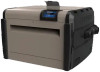
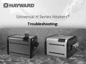
H400FDN Heater
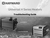
Related Manual Pages


Related Videos

Pool Heaters Gas Best Sellers Winter : Hayward H400FDN Universal H Series 400,000 BTU Pool
Duration: 1:56
Total Views: 32
Duration: 1:56
Total Views: 32
Hayward Pool Heater H400FDN Disassembly Heat Exchanger Repair
Duration: 38:56
Total Views: 13,975
Duration: 38:56
Total Views: 13,975
Pool Heaters Hayward Best Sellers Winter : Hayward H400FDN Universal H Series 400,000 BTU
Duration: 1:56
Total Views: 22
Duration: 1:56
Total Views: 22
Pool Heaters Hayward Best Sellers [ Winter 2018 ]: Hayward H400FDN Universal H-Series 400,000 BTU
Duration: 1:46
Total Views: 134
Duration: 1:46
Total Views: 134
Pool Heaters Gas Best Sellers [ Winter 2018 ]: Hayward H400FDN Universal H-Series 400,000 BTU Pool
Duration: 1:46
Total Views: 883
Duration: 1:46
Total Views: 883
Similar Questions


Hayward H Series Millivolt Propane Pool Heater
Heater won't fire up unless I jump the "th" terminals. Cannot continue with troubleshooting because ...
Heater won't fire up unless I jump the "th" terminals. Cannot continue with troubleshooting because ...
(Posted by Ladylabatt 12 years ago)
Jumped 'th' Terminals And Heater Fired Up. As Soon As I Remove Jumper It Stops
Have trouble with pool heater staying lit. In troubleshooting, I jumped the "th" terminals and it fi...
Have trouble with pool heater staying lit. In troubleshooting, I jumped the "th" terminals and it fi...
(Posted by Ladylabatt 12 years ago)