HP 6830s Remove Keyboard - Compaq Business Notebook
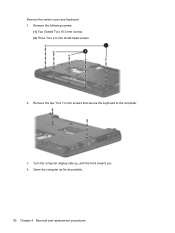
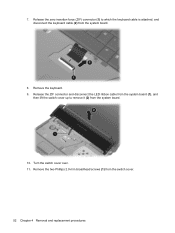
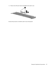
HP 6830s Remove Keyboard
Related Manual Pages


Similar Questions

How To Remove Keyboard From Hp 6830s
(Posted by Swbbb 9 years ago)


Find free HP 6830s - Compaq Business Notebook manuals and user guides available at ManualOwl.com. Try out our unique manual viewer allowing you to interact with manuals from directly within your browser!
View thousands of HP 6830s - Compaq Business Notebook user reviews and customer ratings available at ReviewOwl.com.
Complete HP customer service contact information including steps to reach representatives, hours of operation, customer support links and more from ContactHelp.com.
See detailed HP customer service rankings, employee comments and much more from our sister site.
Find comprehensive HP recall information updated hourly on RecallOwl.com.