
Service Guide
Page 6
.../microphone module 53 Optical drive ...54 Hard drive ...56 TV tuner module ...58 RTC battery ...60 WLAN module ...61 Memory module ...64 Switch cover ...66 Keyboard ...68 Bluetooth module ...71 Speaker assembly ...72 Display assembly ...73 Top cover ...82 Fingerprint reader board ...85 TouchPad on/off button board 86 TouchPad button...
.../microphone module 53 Optical drive ...54 Hard drive ...56 TV tuner module ...58 RTC battery ...60 WLAN module ...61 Memory module ...64 Switch cover ...66 Keyboard ...68 Bluetooth module ...71 Speaker assembly ...72 Display assembly ...73 Top cover ...82 Fingerprint reader board ...85 TouchPad on/off button board 86 TouchPad button...
Service Guide
Page 14
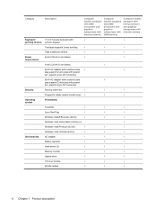
... models equipped with AMD processors and graphics subsystems with UMA memory Computer models equipped with Intel processors and graphics subsystems with discrete memory Keyboard/ 17-inch full-size keyboard with √ √ √ pointing devices numeric keypad Touchpad supports 2-way scrolling √ √ √ Taps enabled as default √ √ √ Power...
... models equipped with AMD processors and graphics subsystems with UMA memory Computer models equipped with Intel processors and graphics subsystems with discrete memory Keyboard/ 17-inch full-size keyboard with √ √ √ pointing devices numeric keypad Touchpad supports 2-way scrolling √ √ √ Taps enabled as default √ √ √ Power...
Service Guide
Page 27
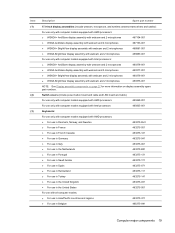
... cable) For use only with computer models equipped with AMD processors 480469-001 For use only with computer models equipped with Intel processors 485605-001 Keyboards: For use only with computer models equipped with AMD processors: ● For use in Denmark, Norway, and Sweden ● For use in France ● For...
... cable) For use only with computer models equipped with AMD processors 480469-001 For use only with computer models equipped with Intel processors 485605-001 Keyboards: For use only with computer models equipped with AMD processors: ● For use in Denmark, Norway, and Sweden ● For use in France ● For...
Service Guide
Page 48
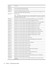
...computer models in Europe, the Middle East, and Africa Keyboard for use only with computer models equipped with AMD processors in the United Kingdom Keyboard for use only with computer models equipped with AMD processors in Germany Keyboard for use only with computer models equipped with AMD ...computer models equipped with AMD processors in Portugal Keyboard for use only with computer models equipped with AMD processors in Turkey Keyboard for use with all computer models in Greece Keyboard for use with all computer models in Latin America Keyboard for use only with computer models equipped with...
...computer models in Europe, the Middle East, and Africa Keyboard for use only with computer models equipped with AMD processors in the United Kingdom Keyboard for use only with computer models equipped with AMD processors in Germany Keyboard for use only with computer models equipped with AMD ...computer models equipped with AMD processors in Portugal Keyboard for use only with computer models equipped with AMD processors in Turkey Keyboard for use with all computer models in Greece Keyboard for use with all computer models in Latin America Keyboard for use only with computer models equipped with...
Service Guide
Page 76
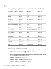
...the power from the computer by first unplugging the power cord from the AC outlet and then unplugging the AC adapter from the computer. 4. Keyboard For use in country or region Spare part number For use in Hibernation, turn the computer on page 66). 68 Chapter 4 Removal and replacement... Kong Italy Israel 483275-AC1 483275-061 483275-BB1 Turkey The United Kingdom The United States 483275-141 483275-031 483275-001 Before removing the keyboard, follow these steps: 1. Remove the switch cover (see Hard drive on page 51). 5. Shut down through the operating system. 2. Remove the battery ...
...the power from the computer by first unplugging the power cord from the AC outlet and then unplugging the AC adapter from the computer. 4. Keyboard For use in country or region Spare part number For use in Hibernation, turn the computer on page 66). 68 Chapter 4 Removal and replacement... Kong Italy Israel 483275-AC1 483275-061 483275-BB1 Turkey The United Kingdom The United States 483275-141 483275-031 483275-001 Before removing the keyboard, follow these steps: 1. Remove the switch cover (see Hard drive on page 51). 5. Shut down through the operating system. 2. Remove the battery ...
Service Guide
Page 77
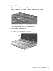
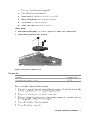
Turn the computer upside down, with the front toward you . 4. Open the computer as far as possible. 5. Remove the keyboard: 1. Remove the Phillips PM2.5×13.0 screw that secure the keyboard to the computer. 3. Remove the three Phillips PM2.0×4.0 screws (1) and the Phillips PM2.0×3.0 broad-head screw (2) that secures the keyboard to the computer. 6. Turn the computer display-side up, with the front toward you . 2. Component replacement procedures 69 Lift the rear edge of the keyboard (1) until it rests at an angle.
Turn the computer upside down, with the front toward you . 4. Open the computer as far as possible. 5. Remove the keyboard: 1. Remove the Phillips PM2.5×13.0 screw that secure the keyboard to the computer. 3. Remove the three Phillips PM2.0×4.0 screws (1) and the Phillips PM2.0×3.0 broad-head screw (2) that secures the keyboard to the computer. 6. Turn the computer display-side up, with the front toward you . 2. Component replacement procedures 69 Lift the rear edge of the keyboard (1) until it rests at an angle.
Service Guide
Page 78
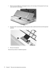
Reverse this procedure to disengage the tabs on the front edge of the keyboard from the top cover and rest it on the display. 8. Slide the keyboard (2) back to install the keyboard. 70 Chapter 4 Removal and replacement procedures Release the ZIF connector (1) to which the keyboard cable is attached and disconnect the keyboard cable (2). 9. 7. Remove the keyboard.
Reverse this procedure to disengage the tabs on the front edge of the keyboard from the top cover and rest it on the display. 8. Slide the keyboard (2) back to install the keyboard. 70 Chapter 4 Removal and replacement procedures Release the ZIF connector (1) to which the keyboard cable is attached and disconnect the keyboard cable (2). 9. 7. Remove the keyboard.
Service Guide
Page 79
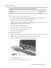
.... 4. Release the Bluetooth module (2) as far as the Bluetooth module cable allows. 3. Disconnect all external devices connected to install the Bluetooth module. Remove the keyboard (see Keyboard on , and then shut it down the computer. Component replacement procedures 71 The Bluetooth module cable is off or in the Cable Kit, spare part...
.... 4. Release the Bluetooth module (2) as far as the Bluetooth module cable allows. 3. Disconnect all external devices connected to install the Bluetooth module. Remove the keyboard (see Keyboard on , and then shut it down the computer. Component replacement procedures 71 The Bluetooth module cable is off or in the Cable Kit, spare part...

Service Guide
Page 80
... Shut down through the operating system. 2. Remove the switch cover (see Switch cover on , and then shut it down the computer. Remove the keyboard (see Battery on page 68). Remove the speaker assembly (3). Remove the three Phillips PM2.5×4.0 screws (2) that secure the speaker assembly to install ...the speaker assembly. 72 Chapter 4 Removal and replacement procedures Remove the battery (see Keyboard on page 51). 5. Reverse this procedure to the computer. 3. Disconnect all external devices connected to the computer. 3.
... Shut down through the operating system. 2. Remove the switch cover (see Switch cover on , and then shut it down the computer. Remove the keyboard (see Battery on page 68). Remove the speaker assembly (3). Remove the three Phillips PM2.5×4.0 screws (2) that secure the speaker assembly to install ...the speaker assembly. 72 Chapter 4 Removal and replacement procedures Remove the battery (see Keyboard on page 51). 5. Reverse this procedure to the computer. 3. Disconnect all external devices connected to the computer. 3.
Service Guide
Page 81
... external devices connected to the computer. 3. Remove the following components: a. Disconnect the display panel cable (1) from the computer. 4. Keyboard (see Speaker assembly on page 72) Remove the display assembly: 1. Speaker assembly (see Keyboard on page 61). 7. Remove the battery (see WLAN module on page 68) c. Component replacement procedures 73 Disconnect the wireless...
... external devices connected to the computer. 3. Remove the following components: a. Disconnect the display panel cable (1) from the computer. 4. Keyboard (see Speaker assembly on page 72) Remove the display assembly: 1. Speaker assembly (see Keyboard on page 61). 7. Remove the battery (see WLAN module on page 68) c. Component replacement procedures 73 Disconnect the wireless...
Service Guide
Page 90
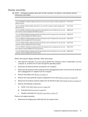
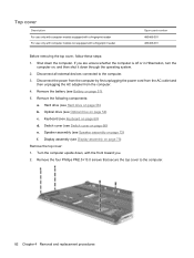
...off or in Hibernation, turn the computer on, and then shut it down the computer. Shut down through the operating system. 2. Keyboard (see Switch cover on page 66) e. Disconnect all external devices connected to the computer. 82 Chapter 4 Removal and replacement procedures Switch cover ...(see Keyboard on page 73) Remove the top cover: 1. Remove the following components: a. Display assembly (see Display assembly on page 68) d. Disconnect...
...off or in Hibernation, turn the computer on, and then shut it down the computer. Shut down through the operating system. 2. Keyboard (see Switch cover on page 66) e. Disconnect all external devices connected to the computer. 82 Chapter 4 Removal and replacement procedures Switch cover ...(see Keyboard on page 73) Remove the top cover: 1. Remove the following components: a. Display assembly (see Display assembly on page 68) d. Disconnect...
Service Guide
Page 93
... assembly on page 68) e. Display assembly (see Keyboard on page 73) g. Remove the battery (see Optical drive on page 51). 5. Optical drive (see Battery on page 54) c. Disconnect the power from the computer ...
... assembly on page 68) e. Display assembly (see Keyboard on page 73) g. Remove the battery (see Optical drive on page 51). 5. Optical drive (see Battery on page 54) c. Disconnect the power from the computer ...
Service Guide
Page 94
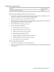
... outlet and then unplugging the AC Adapter from the top cover. Remove the following components: a. Switch cover (see Display assembly on page 56) b. Keyboard (see Hard drive on page 73) g. TouchPad on/off button board Description TouchPad on/off button board, follow these steps: 1. 3. Reverse this... procedure to the computer. 3. Disconnect all external devices connected to install the fingerprint reader board. Hard drive (see Keyboard on /off button board (includes cable) Spare part number 481392-001 Before removing the TouchPad on page 68) e.
... outlet and then unplugging the AC Adapter from the top cover. Remove the following components: a. Switch cover (see Display assembly on page 56) b. Keyboard (see Hard drive on page 73) g. TouchPad on/off button board Description TouchPad on/off button board, follow these steps: 1. 3. Reverse this... procedure to the computer. 3. Disconnect all external devices connected to install the fingerprint reader board. Hard drive (see Keyboard on /off button board (includes cable) Spare part number 481392-001 Before removing the TouchPad on page 68) e.
Service Guide
Page 96
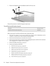
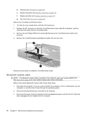
...(1) is attached, and then disconnect the cable from the computer. 88 Chapter 4 Removal and replacement procedures If you . 2. d. Speaker assembly (see Keyboard on /off or in the Cable Kit, spare part number 480474-001. Release the ZIF connector to install the TouchPad button board. Disconnect the power...cord from the AC outlet and then unplugging the AC Adapter from the TouchPad board. 3. Turn the top cover upside down the computer. Keyboard (see Speaker assembly on page 32 for more Cable Kit spare part number information. Remove the TouchPad button board (3) and cables from ...
...(1) is attached, and then disconnect the cable from the computer. 88 Chapter 4 Removal and replacement procedures If you . 2. d. Speaker assembly (see Keyboard on /off or in the Cable Kit, spare part number 480474-001. Release the ZIF connector to install the TouchPad button board. Disconnect the power...cord from the AC outlet and then unplugging the AC Adapter from the TouchPad board. 3. Turn the top cover upside down the computer. Keyboard (see Speaker assembly on page 32 for more Cable Kit spare part number information. Remove the TouchPad button board (3) and cables from ...
Service Guide
Page 97
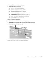
... Bluetooth module cable: 1. 4. Component replacement procedures 89 Switch cover (see Top cover on page 66) d. Remove the Bluetooth module cable (2). Hard drive (see Keyboard on page 56) b. Keyboard (see Hard drive on page 68) e. Remove the Bluetooth module cable (1) from the clips built into the top cover. 3. Display assembly (see Optical drive...
... Bluetooth module cable: 1. 4. Component replacement procedures 89 Switch cover (see Top cover on page 66) d. Remove the Bluetooth module cable (2). Hard drive (see Keyboard on page 56) b. Keyboard (see Hard drive on page 68) e. Remove the Bluetooth module cable (1) from the clips built into the top cover. 3. Display assembly (see Optical drive...

Service Guide
Page 98
...Australia and New Zealand For use only in Hibernation, turn the computer on, and then shut it down the computer. Display assembly (see Keyboard on page 73) g. Description Modem module for use in all external devices connected to the system board. 90 Chapter 4 Removal and ...replacement procedures If you are unsure whether the computer is included in the Cable Kit, spare part number 480474-001. Remove the following components: a. Keyboard (see Display assembly on page 68) e. Shut down through the operating system. 2. Remove the battery (see Optical drive on page 51). 5. ...
...Australia and New Zealand For use only in Hibernation, turn the computer on, and then shut it down the computer. Display assembly (see Keyboard on page 73) g. Description Modem module for use in all external devices connected to the system board. 90 Chapter 4 Removal and ...replacement procedures If you are unsure whether the computer is included in the Cable Kit, spare part number 480474-001. Remove the following components: a. Keyboard (see Display assembly on page 68) e. Shut down through the operating system. 2. Remove the battery (see Optical drive on page 51). 5. ...
Service Guide
Page 100
Switch cover (see Switch cover on page 68) e. Keyboard (see Battery on page 72) g. Remove the battery (see Keyboard on page 66) d. Speaker assembly (see Bluetooth module on page 56) c. Bluetooth module (see Speaker assembly on page 51). 5. Hard drive (see Processor on page ...
Switch cover (see Switch cover on page 68) e. Keyboard (see Battery on page 72) g. Remove the battery (see Keyboard on page 66) d. Speaker assembly (see Bluetooth module on page 56) c. Bluetooth module (see Speaker assembly on page 51). 5. Hard drive (see Processor on page ...

Service Guide
Page 102
... Top cover on page 51). 5. Optical drive (see Speaker assembly on page 54) c. Speaker assembly (see Optical drive on page 72) f. Keyboard (see Display assembly on page 68) e. Display assembly (see Keyboard on page 73) g. Reverse this procedure to the computer. 3. Shut down through the operating system. 2. Remove the following components: a. Disconnect...
... Top cover on page 51). 5. Optical drive (see Speaker assembly on page 54) c. Speaker assembly (see Optical drive on page 72) f. Keyboard (see Display assembly on page 68) e. Display assembly (see Keyboard on page 73) g. Reverse this procedure to the computer. 3. Shut down through the operating system. 2. Remove the following components: a. Disconnect...
Service Guide
Page 103
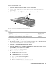
... computer by first unplugging the power cord from the AC outlet and then unplugging the AC Adapter from the base enclosure. Speaker assembly (see Keyboard on page 72) Component replacement procedures 95 Lift the audio/infrared board (3) straight up to the base enclosure. 3. Remove the two Phillips ...If you are unsure whether the computer is off or in Hibernation, turn the computer on, and then shut it from the computer. 4. Keyboard (see Speaker assembly on page 68) e. USB board Description USB board for use only with computer models equipped with AMD processors USB board for...
... computer by first unplugging the power cord from the AC outlet and then unplugging the AC Adapter from the base enclosure. Speaker assembly (see Keyboard on page 72) Component replacement procedures 95 Lift the audio/infrared board (3) straight up to the base enclosure. 3. Remove the two Phillips ...If you are unsure whether the computer is off or in Hibernation, turn the computer on, and then shut it from the computer. 4. Keyboard (see Speaker assembly on page 68) e. USB board Description USB board for use only with computer models equipped with AMD processors USB board for...
Service Guide
Page 105
... is off or in Hibernation, turn the computer on page 68) e. c. Display assembly (see Speaker assembly on page 73) g. Shut down through the operating system. 2. Keyboard (see Keyboard on , and then shut it down the computer.
... is off or in Hibernation, turn the computer on page 68) e. c. Display assembly (see Speaker assembly on page 73) g. Shut down through the operating system. 2. Keyboard (see Keyboard on , and then shut it down the computer.


