End User License Agreement
Page 2
... This EULA applies to updates or supplements to the original Software Product provided by HP unless HP provides other terms along with /for commercial timesharing or bureau use of any other form, may not reverse engineer, decompile, or disassemble the Software Product, except and only to the extent that... HP and its suppliers and are owned by HP or its affiliates may not sublicense, assign or transfer the license or Software Product except...
... This EULA applies to updates or supplements to the original Software Product provided by HP unless HP provides other terms along with /for commercial timesharing or bureau use of any other form, may not reverse engineer, decompile, or disassemble the Software Product, except and only to the extent that... HP and its suppliers and are owned by HP or its affiliates may not sublicense, assign or transfer the license or Software Product except...

Reference Guide
Page 2
.... patents and other intellectual property rights owned by Microsoft Corporation, Phoenix Technologies, Ltd., ATI Technologies Inc., Intel Corporation, and Adobe Systems Incorporated. Reverse engineering or disassembly is also prohibited. Pentium® and the Intel Inside logo are trademarks of the programs that control this copyright protection technology must be authorized by...
.... patents and other intellectual property rights owned by Microsoft Corporation, Phoenix Technologies, Ltd., ATI Technologies Inc., Intel Corporation, and Adobe Systems Incorporated. Reverse engineering or disassembly is also prohibited. Pentium® and the Intel Inside logo are trademarks of the programs that control this copyright protection technology must be authorized by...

Reference Guide
Page 107
... recycling of batteries. • To obtain a replacement battery, contact your battery pack, do not allow a metal object to touch the battery contacts. • Do not disassemble the battery. Department of -life. There are recommended: • Ensure proper use by the manufacturer. • This product contains a lithium-ion or nickel-metal-hydride...
... recycling of batteries. • To obtain a replacement battery, contact your battery pack, do not allow a metal object to touch the battery contacts. • Do not disassemble the battery. Department of -life. There are recommended: • Ensure proper use by the manufacturer. • This product contains a lithium-ion or nickel-metal-hydride...

Maintenance and Service Guide
Page 3
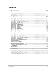
Contents Introduction...vii Product Information...1-1 Features ...1-8 Operation...1-14 Specifications ...1-18 Internal Design...1-24 Removal and Replacement 2-1 Disassembly Flowchart ...2-3 Removing the Battery ...2-4 Removing an SDRAM Module...2-5 Removing the Wireless LAN Mini PCI Card 2-7 Removing the Hard Disk Drive...2-9 Recovering the Factory Software...2-11 ...
Contents Introduction...vii Product Information...1-1 Features ...1-8 Operation...1-14 Specifications ...1-18 Internal Design...1-24 Removal and Replacement 2-1 Disassembly Flowchart ...2-3 Removing the Battery ...2-4 Removing an SDRAM Module...2-5 Removing the Wireless LAN Mini PCI Card 2-7 Removing the Hard Disk Drive...2-9 Recovering the Factory Software...2-11 ...

Maintenance and Service Guide
Page 4
Figures Figure 1-1. Front View...1-8 Figure 1-2. Bottom View...1-10 Figure 1-4. Resetting the Notebook ...1-17 Figure 1-8. Removing the Battery ...2-4 Figure 2-3. Removing an SDRAM Module 2-5 Figure 2-4. Removing the Mini PCI Card 2-7 Figure 2-6. Removing the Keyboard ...Case Screws 2-30 Figure 2-21. AMD CPU Module Release 2-47 Figure 2-30. Removing the Motherboard 2-51 Figure 2-35. Back View ...1-12 Figure 1-6. Disassembly Flow...2-3 Figure 2-2. Removing the Top Case Screws 2-29 Figure 2-20. Removing the Audio PCA ...2-39 Figure 2-26. Removing the RJ11/1394 Connector Module...
Figures Figure 1-1. Front View...1-8 Figure 1-2. Bottom View...1-10 Figure 1-4. Resetting the Notebook ...1-17 Figure 1-8. Removing the Battery ...2-4 Figure 2-3. Removing an SDRAM Module 2-5 Figure 2-4. Removing the Mini PCI Card 2-7 Figure 2-6. Removing the Keyboard ...Case Screws 2-30 Figure 2-21. AMD CPU Module Release 2-47 Figure 2-30. Removing the Motherboard 2-51 Figure 2-35. Back View ...1-12 Figure 1-6. Disassembly Flow...2-3 Figure 2-2. Removing the Top Case Screws 2-29 Figure 2-20. Removing the Audio PCA ...2-39 Figure 2-26. Removing the RJ11/1394 Connector Module...

Maintenance and Service Guide
Page 33
Figure 2-1. Disassembly Flow Service Manual Removal and Replacement 2-3 Disassembly Flowchart The following diagram shows the general "path" you will use when disassembling the notebook to access any particular component.
Figure 2-1. Disassembly Flow Service Manual Removal and Replacement 2-3 Disassembly Flowchart The following diagram shows the general "path" you will use when disassembling the notebook to access any particular component.
Service Manual
Page 3
Contents Product Information...1-1 Features ...1-48 Operation ...1-54 Specifications ...1-58 Internal Design ...1-64 Removal and Replacement 2-1 Disassembly Flowchart ...2-3 Removing the Battery...2-4 Removing a SDRAM Module...2-5 Removing the Wireless LAN Mini-PCI Card 2-7 Removing the Hard Disk Drive...2-9 Replacing Small Parts ...2-11 Removing the ...
Contents Product Information...1-1 Features ...1-48 Operation ...1-54 Specifications ...1-58 Internal Design ...1-64 Removal and Replacement 2-1 Disassembly Flowchart ...2-3 Removing the Battery...2-4 Removing a SDRAM Module...2-5 Removing the Wireless LAN Mini-PCI Card 2-7 Removing the Hard Disk Drive...2-9 Replacing Small Parts ...2-11 Removing the ...

Service Manual
Page 4
...the Top Case Screws 2-30 Figure 2-21. Removing the Audio PCA 2-39 Figure 2-26. Removing a PCMCIA Door 2-60 Figure 2-38. Disassembly Flow ...2-3 Figure 2-2. Removing the Mini-PCI Card 2-7 Figure 2-6. Removing the Switchboard PCA 2-18 Figure 2-14. Removing the Display Assembly 2-...25. Boot-Block Jumper ...2-62 Figure 3-1. Removing the Keyboard 2-17 Figure 2-13. Removing the Floppy Drive 2-35 Figure 2-24. Resetting the Notebook 1-57 Figure 1-8. Exploded View...4-2 Figure 4-2. Removing the Hard Disk Drive 2-9 Figure 2-8. Removing the CD/DVD Drive 2-21 Figure 2-16. ...
...the Top Case Screws 2-30 Figure 2-21. Removing the Audio PCA 2-39 Figure 2-26. Removing a PCMCIA Door 2-60 Figure 2-38. Disassembly Flow ...2-3 Figure 2-2. Removing the Mini-PCI Card 2-7 Figure 2-6. Removing the Switchboard PCA 2-18 Figure 2-14. Removing the Display Assembly 2-...25. Boot-Block Jumper ...2-62 Figure 3-1. Removing the Keyboard 2-17 Figure 2-13. Removing the Floppy Drive 2-35 Figure 2-24. Resetting the Notebook 1-57 Figure 1-8. Exploded View...4-2 Figure 4-2. Removing the Hard Disk Drive 2-9 Figure 2-8. Removing the CD/DVD Drive 2-21 Figure 2-16. ...

Service Manual
Page 74
Figure 2-1. Disassembly Flowchart The following diagram shows the general "path" you will use when disassembling the notebook to access any particular component. Disassembly Flow Service Manual Removal and Replacement 2-3
Figure 2-1. Disassembly Flowchart The following diagram shows the general "path" you will use when disassembling the notebook to access any particular component. Disassembly Flow Service Manual Removal and Replacement 2-3


