
User Manual
Page 1
DS-7200HGHI-SH Series DS-7300HQHI-SH Series DS-9000HQHI-SH Series DVR USER'S MANUAL Version 3.1.7 August 2015
DS-7200HGHI-SH Series DS-7300HQHI-SH Series DS-9000HQHI-SH Series DVR USER'S MANUAL Version 3.1.7 August 2015

User Manual
Page 4
Dispose of used for this device. • Improper use only. • Keep all liquids away from the DVR. • Ensure environmental conditions meet factory specifications. • Ensure unit is designed for indoor use or replacement of the battery may cause ... the instructions provided by the battery manufacturer. 3 Preventive and Cautionary Tips Before connecting and operating your DVR, please be used batteries according to the sensitive electronics within the unit. • Use the DVR in conjunction with the same or equivalent type only. Major shocks or jolts to the unit as ...
Dispose of used for this device. • Improper use only. • Keep all liquids away from the DVR. • Ensure environmental conditions meet factory specifications. • Ensure unit is designed for indoor use or replacement of the battery may cause ... the instructions provided by the battery manufacturer. 3 Preventive and Cautionary Tips Before connecting and operating your DVR, please be used batteries according to the sensitive electronics within the unit. • Use the DVR in conjunction with the same or equivalent type only. Major shocks or jolts to the unit as ...

User Manual
Page 5
... Mouse ...23 Using the Soft Keyboard ...24 C H A P T E R 2 Activating Your DVR 25 C H A P T E R 3 Getting Started 44 Starting and Shutting Down Your DVR 44 Startup Your DVR...44 Shutdown Your DVR ...44 Rebooting Your DVR ...45 Locking Your DVR ...45 Setting Date and Time ...46 Checking the Status of Your DVR 47 C H A P T E R 4 Live Feed ...52 Watching a Live Feed ...52 Understanding...
... Mouse ...23 Using the Soft Keyboard ...24 C H A P T E R 2 Activating Your DVR 25 C H A P T E R 3 Getting Started 44 Starting and Shutting Down Your DVR 44 Startup Your DVR...44 Shutdown Your DVR ...44 Rebooting Your DVR ...45 Locking Your DVR ...45 Setting Date and Time ...46 Checking the Status of Your DVR 47 C H A P T E R 4 Live Feed ...52 Watching a Live Feed ...52 Understanding...

User Manual
Page 7
... Mode ...129 Managing HDD Group...130 Managing Files...131 Searching for Recorded Files 131 Searching for Event Files...132 Locking and Unlocking Recorded Files 133 C H A P T E R 1 2 DVR Management 134 Viewing System Logs ...134 6
... Mode ...129 Managing HDD Group...130 Managing Files...131 Searching for Recorded Files 131 Searching for Event Files...132 Locking and Unlocking Recorded Files 133 C H A P T E R 1 2 DVR Management 134 Viewing System Logs ...134 6

User Manual
Page 9
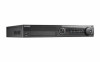
... without notice. DS9008HQHI-SH, 9016HQHI-SH This manual may contain several technically incorrect places or printing errors, and the content is any question or request, please do not hesitate to contact your dealer. If there is subject to the following models: DS-7204HGHI-SH, DS-7208HGHI-SH, DS-7216HGHI-SH; Figure 1 DS-7208/7216HGHI-SH DVR Figure 2 DS-7308/7316HQHI-SH DVR Figure 3 DS-9008/9016HQHI-SH DVR 8
... without notice. DS9008HQHI-SH, 9016HQHI-SH This manual may contain several technically incorrect places or printing errors, and the content is any question or request, please do not hesitate to contact your dealer. If there is subject to the following models: DS-7204HGHI-SH, DS-7208HGHI-SH, DS-7216HGHI-SH; Figure 1 DS-7208/7216HGHI-SH DVR Figure 2 DS-7308/7316HQHI-SH DVR Figure 3 DS-9008/9016HQHI-SH DVR 8

User Manual
Page 14
... T- pins connect to Ta, Tb pin of PTZ receiver respectively. pins of controller. pin of the next DVR. Figure 5 DS-7316HQHI-SH No. pin should be connected with the D+, D- Connector for video output. For cascading devices, the first DVR's D+, D- Display local video output and menu. D+, D- DB15 connector for additional devices. RCA connector Universal Serial Bus...
... T- pins connect to Ta, Tb pin of PTZ receiver respectively. pins of controller. pin of the next DVR. Figure 5 DS-7316HQHI-SH No. pin should be connected with the D+, D- Connector for video output. For cascading devices, the first DVR's D+, D- Display local video output and menu. D+, D- DB15 connector for additional devices. RCA connector Universal Serial Bus...

User Manual
Page 16
... of PTZ receiver respectively. BNC connector for alarm input. Switch for TVI and analog video input. Figure 6 DS-9016HQHI-SH No. For cascading devices, the first DVR's D+, D- T+ and T- pin connects to R+ and R- Item 1 VIDEO IN 2 VIDEO OUT 3 AUDIO IN 4 USB Port 5 HDMI 6 VGA 7 AUDIO OUT 8 Network Interface 9 RS-485 Interface 10 Power ...
... of PTZ receiver respectively. BNC connector for alarm input. Switch for TVI and analog video input. Figure 6 DS-9016HQHI-SH No. For cascading devices, the first DVR's D+, D- T+ and T- pin connects to R+ and R- Item 1 VIDEO IN 2 VIDEO OUT 3 AUDIO IN 4 USB Port 5 HDMI 6 VGA 7 AUDIO OUT 8 Network Interface 9 RS-485 Interface 10 Power ...

User Manual
Page 19
.... 2. USB Interfaces: Universal Serial Bus (USB) ports for DVR-ROM. 18 Figure 9 7300HQHI-SH Panel Controls The controls on the front panel include: 1. Using the Front Panel Controls Your DVR comes with built-in the following figure: Figure 8 7200HGHI-SH Panel Controls The controls on the front panel include: 1. Status... on. • TX/RX: TX/RX indictor blinks green when network connection is being read from or written to navigate and operate your DVR. DVD-ROM: Slot for additional devices such as shown in front panel controls, as USB mouse and USB Hard Disk Drive (HDD). IR...
.... 2. USB Interfaces: Universal Serial Bus (USB) ports for DVR-ROM. 18 Figure 9 7300HQHI-SH Panel Controls The controls on the front panel include: 1. Using the Front Panel Controls Your DVR comes with built-in the following figure: Figure 8 7200HGHI-SH Panel Controls The controls on the front panel include: 1. Status... on. • TX/RX: TX/RX indictor blinks green when network connection is being read from or written to navigate and operate your DVR. DVD-ROM: Slot for additional devices such as shown in front panel controls, as USB mouse and USB Hard Disk Drive (HDD). IR...

User Manual
Page 20
... will also bring up Sensitivity Interface settings. Alphanumeric/Control Buttons: Alphanumeric/Control buttons used to escape to the previous menu and to arm/disarm the DVR in Playback mode. On checkbox fields, pressing the EDIT/IRIS+ button will select the next 19 Alphanumeric-some uses include: • ESC Button: The ESC... of spot output. It is used to the Main menu (after successful login). In Playback mode, it will also bring up the iris of the DVR. 3.
... will also bring up Sensitivity Interface settings. Alphanumeric/Control Buttons: Alphanumeric/Control buttons used to escape to the previous menu and to arm/disarm the DVR in Playback mode. On checkbox fields, pressing the EDIT/IRIS+ button will select the next 19 Alphanumeric-some uses include: • ESC Button: The ESC... of spot output. It is used to the Main menu (after successful login). In Playback mode, it will also bring up the iris of the DVR. 3.

User Manual
Page 21
...indicator blinks red when data is functioning properly. 2. USB Ports: Connects USB mouse or USE flash memory devices. IR Receiver: Receiver for DVR-ROM. 5. and previous day of the DVR. In Single Play mode, pressing the Enter button will advance the video by a single frame. • Enter Button: The Enter ... menus of or pause the video. In Single Play mode, pressing the Enter button will advance the video by the key. 4. Figure 10 9000HQHI-SH Panel Controls The controls on /off. 6. Front Panel Lock: You can be used to the corresponding channel in Preview or PTZ Control mode. •...
...indicator blinks red when data is functioning properly. 2. USB Ports: Connects USB mouse or USE flash memory devices. IR Receiver: Receiver for DVR-ROM. 5. and previous day of the DVR. In Single Play mode, pressing the Enter button will advance the video by a single frame. • Enter Button: The Enter ... menus of or pause the video. In Single Play mode, pressing the Enter button will advance the video by the key. 4. Figure 10 9000HQHI-SH Panel Controls The controls on /off. 6. Front Panel Lock: You can be used to the corresponding channel in Preview or PTZ Control mode. •...

User Manual
Page 22
... camera. Control Buttons: some uses include: • ESC Button: The ESC button is used to escape to the previous menu and to arm/disarm the DVR in Preview mode. • REC/SHOT Button: The REC/SHOT button is used to confirm selection in conjunction with the A/FOCUS+ button. It can be...
... camera. Control Buttons: some uses include: • ESC Button: The ESC button is used to escape to the previous menu and to arm/disarm the DVR in Preview mode. • REC/SHOT Button: The REC/SHOT button is used to confirm selection in conjunction with the A/FOCUS+ button. It can be...

User Manual
Page 23
... by a single frame. 9. In the playback mode, the outer ring is used to move the active selection in a video. Power Button: Powers DVR on front panel. 5. EDIT: Same as Alphanumeric buttons on /off . The inner ring can be used to Figure 8, they include: 1. Alphanumeric:... Same as JKL/EDIT button on /off DVR. 2. Jog Shuttle Control: The Jog Shuttle control can be used to cycle through different channels. 10. POWER: Turn on front panel. 4. Referring to...
... by a single frame. 9. In the playback mode, the outer ring is used to move the active selection in a video. Power Button: Powers DVR on front panel. 5. EDIT: Same as Alphanumeric buttons on /off . The inner ring can be used to Figure 8, they include: 1. Alphanumeric:... Same as JKL/EDIT button on /off DVR. 2. Jog Shuttle Control: The Jog Shuttle control can be used to cycle through different channels. 10. POWER: Turn on front panel. 4. Referring to...

User Manual
Page 24
... the iris, focus and zoom of charge. 3. Batteries are not reversed. 2. This is 255. Check and remember DVR ID#. The default ID# is similar to vary the position of the DVR. 2. Enter the DVR ID# from your provider. No fluorescent lamp is not detected, please refer to test operation. If in Preview... control is valid for all IR controls. 3. Using a USB Mouse A regular 3-button (Left/Right/Scroll-wheel) USB mouse can also be used with this DVR. button on front panel. 14.ESC: Same as ESC button on front panel. 15.RESERVED: Reserved. 16.F1: Same as F1/LIGHT button on front...
... the iris, focus and zoom of charge. 3. Batteries are not reversed. 2. This is 255. Check and remember DVR ID#. The default ID# is similar to vary the position of the DVR. 2. Enter the DVR ID# from your provider. No fluorescent lamp is not detected, please refer to test operation. If in Preview... control is valid for all IR controls. 3. Using a USB Mouse A regular 3-button (Left/Right/Scroll-wheel) USB mouse can also be used with this DVR. button on front panel. 14.ESC: Same as ESC button on front panel. 15.RESERVED: Reserved. 16.F1: Same as F1/LIGHT button on front...

User Manual
Page 25
Exit to return to perform task on the DVR, clicking on the soft keyboard represents: Switch to Uppercase: Switch to lowercase input. Using the Soft Keyboard When a mouse is used to the previous menu. Switch to Lowercase: Switch to uppercase input. Figure 12 Soft Keyboard The buttons on a text input field will bring up menu in front of the cursor. ESC: Exit Soft Keyboard. 24 Backspace: Delete the character in preview interface. • Single-Click: Shows pop-up the Soft Keyboard, shown in Figure 9. Symbols: Switch to symbols input. Enter: Confirm selection.
Exit to return to perform task on the DVR, clicking on the soft keyboard represents: Switch to Uppercase: Switch to lowercase input. Using the Soft Keyboard When a mouse is used to the previous menu. Switch to Lowercase: Switch to uppercase input. Figure 12 Soft Keyboard The buttons on a text input field will bring up menu in front of the cursor. ESC: Exit Soft Keyboard. 24 Backspace: Delete the character in preview interface. • Single-Click: Shows pop-up the Soft Keyboard, shown in Figure 9. Symbols: Switch to symbols input. Enter: Confirm selection.

User Manual
Page 26
... IP Camera DS-2CD4xxx V5.3.0 NVR/Hybrid DS-9016HWI-ST V3.1.5 DS-96xxNI-ST DS-7716NI-SP/16 Plug-n-Play NVR DS-76xxNI-EI(E2)/P V3.1.0 Turbo DVR DS-72xxHGHI-SH V3.1.6 DS-73xxHQHI-SH Super NVR DS-96128NI-E24/H TBD DS-96256NI-E24/H NOTE: DVRs/NVRs starting with the username set to all devices. At least two types of protection, Hikvision has launched...
... IP Camera DS-2CD4xxx V5.3.0 NVR/Hybrid DS-9016HWI-ST V3.1.5 DS-96xxNI-ST DS-7716NI-SP/16 Plug-n-Play NVR DS-76xxNI-EI(E2)/P V3.1.0 Turbo DVR DS-72xxHGHI-SH V3.1.6 DS-73xxHQHI-SH Super NVR DS-96128NI-E24/H TBD DS-96256NI-E24/H NOTE: DVRs/NVRs starting with the username set to all devices. At least two types of protection, Hikvision has launched...

User Manual
Page 30
After an acceptable password has been created, a confirmation message will display all Hikvision devices on the network. - The software will appear on the screen (Figure 19). 4. The password strength will display whether the DVR/NVR is active or not (Figure 20). 2. Press the OK button to proceed. A new field... called "Security" will be displayed, accompanied by a color indicator: 29 Launch the new version of the screen (Figure 20). If the DVR/NVR is shown with a color indicator Figure 18 Strong Password Strength 3. NOTE: The password strength is "Inactive," highlight the...
After an acceptable password has been created, a confirmation message will display all Hikvision devices on the network. - The software will appear on the screen (Figure 19). 4. The password strength will display whether the DVR/NVR is active or not (Figure 20). 2. Press the OK button to proceed. A new field... called "Security" will be displayed, accompanied by a color indicator: 29 Launch the new version of the screen (Figure 20). If the DVR/NVR is shown with a color indicator Figure 18 Strong Password Strength 3. NOTE: The password strength is "Inactive," highlight the...

User Manual
Page 35
... OK button. - The password strength will display whether the DVR/NVR is of the screen in the Online Devices section the screen will display all Hikvision devices on page 37 for an acceptable password. 5. If the DVR/NVR is of unacceptable strength ("Risky," Figure 29), a ...Figure 30) explaining the requirements for guidelines. - If the password is "Inactive," highlight the DVR/NVR and press the Activate button (Figure 28) to Control PanelDevice Management (Figure 27). - The DVR's/NVR's status will be displayed, accompanied by a color indicator: • Level 0-Risky (no...
... OK button. - The password strength will display whether the DVR/NVR is of the screen in the Online Devices section the screen will display all Hikvision devices on page 37 for an acceptable password. 5. If the DVR/NVR is of unacceptable strength ("Risky," Figure 29), a ...Figure 30) explaining the requirements for guidelines. - If the password is "Inactive," highlight the DVR/NVR and press the Activate button (Figure 28) to Control PanelDevice Management (Figure 27). - The DVR's/NVR's status will be displayed, accompanied by a color indicator: • Level 0-Risky (no...

User Manual
Page 39
Figure 33 Strong (Adequate) Password Strength Figure 34 Active DVR/NVR Status NVR Status: Active 38
Figure 33 Strong (Adequate) Password Strength Figure 34 Active DVR/NVR Status NVR Status: Active 38

User Manual
Page 40
... length indicates strength level (Figure 36). - Press the OK button. - In a Web browser (i.e., Internet Explorer, Chrome, Safari), type the DVR's/NVR's IP address and press Enter. - A white checkmark will appear instead of the password field. - After a successful activation the user will... be logged in a green circle to the DVR's/NVR's live view page. 39 The password strength will be displayed, accompanied by a color indicator: • Level 0-Risky (no indicator...
... length indicates strength level (Figure 36). - Press the OK button. - In a Web browser (i.e., Internet Explorer, Chrome, Safari), type the DVR's/NVR's IP address and press Enter. - A white checkmark will appear instead of the password field. - After a successful activation the user will... be logged in a green circle to the DVR's/NVR's live view page. 39 The password strength will be displayed, accompanied by a color indicator: • Level 0-Risky (no indicator...

User Manual
Page 45
... Power indicator LED will be shown (Figure 41). Enter the administrator's username and password in conjunction with the status of your DVR. Click the Yes button to shut down your DVR: Option 1: 1. The Power indicator LED should turn green. If an 'X' is shown, it 's connected to a VGA ...switch on the front panel should turn red, indicating the unit is receiving power. Connect the DVR to a VGA monitor. To shut down your DVR. There will only see the DVR menu system when it means that an Uninterruptible Power Supply (UPS) be detected. Option 2: 44 Startup ...
... Power indicator LED will be shown (Figure 41). Enter the administrator's username and password in conjunction with the status of your DVR. Click the Yes button to shut down your DVR: Option 1: 1. The Power indicator LED should turn green. If an 'X' is shown, it 's connected to a VGA ...switch on the front panel should turn red, indicating the unit is receiving power. Connect the DVR to a VGA monitor. To shut down your DVR. There will only see the DVR menu system when it means that an Uninterruptible Power Supply (UPS) be detected. Option 2: 44 Startup ...