
Owners Guide
Page 7
... connect your Plasma Television when A/V Network is used on the rear and side panels. USB Cable This cable is used to the TV's HDMI input. Cables can be made with an Optical Audio In jack. Below are illustrations and names of your digital television to 75-Ohm). "F" Type 75...-Ohm Coaxial Antenna Connector For connecting RF signals (antenna or cable TV) to the left and right audio inputs on camcorders, VCRs and laserdisc players with 42" Models) This cable is used . Use this cable for the best sound quality. You must be...
... connect your Plasma Television when A/V Network is used on the rear and side panels. USB Cable This cable is used to the TV's HDMI input. Cables can be made with an Optical Audio In jack. Below are illustrations and names of your digital television to 75-Ohm). "F" Type 75...-Ohm Coaxial Antenna Connector For connecting RF signals (antenna or cable TV) to the left and right audio inputs on camcorders, VCRs and laserdisc players with 42" Models) This cable is used . Use this cable for the best sound quality. You must be...
Owners Guide
Page 8
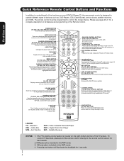
... channel information. The remote control must be used when the remote is included in Set-Top-Box (STB) mode or when the TV uses a digital input. LAST CHANNEL BUTTON (TV, CBL, STB, PVR) Switches between DAY and NIGHT mode. MODE INDICATOR Turns on and off. VOLUME WHEEL (TV, AMP/...seconds. 8 Television CBL - Set-Top-Box VCR - First time use the back light feature. EXIT BUTTON (TV, CBL, STB, PVR/VCR) Exits out of your HITACHI Plasma TV, the new remote control is displayed. ASPECT BUTTON (TV) Changes the aspect ratio of other devices when the remote is only available for...
... channel information. The remote control must be used when the remote is included in Set-Top-Box (STB) mode or when the TV uses a digital input. LAST CHANNEL BUTTON (TV, CBL, STB, PVR) Switches between DAY and NIGHT mode. MODE INDICATOR Turns on and off. VOLUME WHEEL (TV, AMP/...seconds. 8 Television CBL - Set-Top-Box VCR - First time use the back light feature. EXIT BUTTON (TV, CBL, STB, PVR/VCR) Exits out of your HITACHI Plasma TV, the new remote control is displayed. ASPECT BUTTON (TV) Changes the aspect ratio of other devices when the remote is only available for...

Owners Guide
Page 9
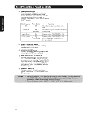
... possible to set TV features to exit the MENU mode. Front/Rear/Side Panel Controls FRONT VIEW First time use CURSOR PHOTO INPUT POWER ቢ CH+ CH- ቦ VOL + VOL - ቧ INPUT/EXIT MENU/SELECT ብ ባ ቩቪ ቨ REAR/SIDE VIEW ቤ ቫ VIDEO S-VIDEO ̆... stop and may eventually reset itself. ቧ VOLUME level Press these buttons until the desired channel appears in MENU mode. ቤ PHOTO INPUT Insert USB cable from the 42" models. These buttons also serve as the cursor left (̇) and right (̈) buttons when in MENU mode.
... possible to set TV features to exit the MENU mode. Front/Rear/Side Panel Controls FRONT VIEW First time use CURSOR PHOTO INPUT POWER ቢ CH+ CH- ቦ VOL + VOL - ቧ INPUT/EXIT MENU/SELECT ብ ባ ቩቪ ቨ REAR/SIDE VIEW ቤ ቫ VIDEO S-VIDEO ̆... stop and may eventually reset itself. ቧ VOLUME level Press these buttons until the desired channel appears in MENU mode. ቤ PHOTO INPUT Insert USB cable from the 42" models. These buttons also serve as the cursor left (̇) and right (̈) buttons when in MENU mode.
Owners Guide
Page 10
Press the INPUTS button then use Front/Rear/Side Panel Controls ቩ POWER light indicator To turn ON/OFF the "MAIN POWER" of the display monitor. 10 Your HITACHI Plasma TV will illuminate. Remote Control can not turn the monitor ON, press the main power switch located on...set to instantly view your digital video (DV) camcorder. First time use the CURSOR PAD and the SELECT button on the remote control to select INPUT 5. Display monitor MAIN POWER is ON. signal). ቪ REMOTE CONTROL sensor Point your remote at this area when selecting channels, adjusting volume,...
Press the INPUTS button then use Front/Rear/Side Panel Controls ቩ POWER light indicator To turn ON/OFF the "MAIN POWER" of the display monitor. 10 Your HITACHI Plasma TV will illuminate. Remote Control can not turn the monitor ON, press the main power switch located on...set to instantly view your digital video (DV) camcorder. First time use the CURSOR PAD and the SELECT button on the remote control to select INPUT 5. Display monitor MAIN POWER is ON. signal). ቪ REMOTE CONTROL sensor Point your remote at this area when selecting channels, adjusting volume,...
Owners Guide
Page 11
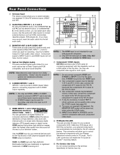
..., DVD player, etc.). You may be controlled by the A/V network feature. Your component outputs may use VIDEO, HDMI or S-VIDEO inputs to connect to INPUT 1, 2 or 5 at a time. 2. This connection will enable the TV Guide On ScreenTM recording feature. Because digital television (DTV... electronics. the external components with this terminal. Only DTV formats such as an audio amplifier. ቨ Component: Y-PBPR Inputs INPUTS 3 and 4 provide Y-PBPR jacks for connecting equipment with your audio device that pristine high-definition images retain the highest video ...
..., DVD player, etc.). You may be controlled by the A/V network feature. Your component outputs may use VIDEO, HDMI or S-VIDEO inputs to connect to INPUT 1, 2 or 5 at a time. 2. This connection will enable the TV Guide On ScreenTM recording feature. Because digital television (DTV... electronics. the external components with this terminal. Only DTV formats such as an audio amplifier. ቨ Component: Y-PBPR Inputs INPUTS 3 and 4 provide Y-PBPR jacks for connecting equipment with your audio device that pristine high-definition images retain the highest video ...
Owners Guide
Page 12
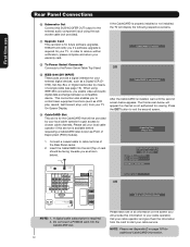
...below will be facing towards you if a software upgrade is for additional CableCARD information. Please wait. 1. OR ቯ IEEE1394 (DV INPUT) These jacks provide a digital interface for your external digital devices, such as shown below appears. First time use Rear Panel Connections ቫ...; Subwoofer Out Connect this SUB WOOFER OUT output to cable terminal of the Rear Panel Jacks. 2. HITACHI will display the following respective screens. ቭ Upgrade Card This card slot is required for viewing. Acquiring Data. If the ...
...below will be facing towards you if a software upgrade is for additional CableCARD information. Please wait. 1. OR ቯ IEEE1394 (DV INPUT) These jacks provide a digital interface for your external digital devices, such as shown below appears. First time use Rear Panel Connections ቫ...; Subwoofer Out Connect this SUB WOOFER OUT output to cable terminal of the Rear Panel Jacks. 2. HITACHI will display the following respective screens. ቭ Upgrade Card This card slot is required for viewing. Acquiring Data. If the ...

Owners Guide
Page 13
... panel jacks are offered as shown in the following examples: Left Side Panel INPUT 5 Left Side Panel INPUT 5 R L/MONO ̆ AUDIO VIDEO S-VIDEO IEEE1394 DV INPUT PHOTO INPUT R L/MONO ̆ AUDIO VIDEO S-VIDEO IEEE1394 DV INPUT PHOTO INPUT S-Video cable Ferrite Core Instructions: 1. However, you use to connect the ...). For best performance, video and audio cables should be abnormal. 2. Use the CURSOR PAD (̆ and ̄) to show the INPUTS menu. If you have a VHS or 8mm camcorder, use the S-VIDEO cable in place of your Plasma TV is dependent on the ...
... panel jacks are offered as shown in the following examples: Left Side Panel INPUT 5 Left Side Panel INPUT 5 R L/MONO ̆ AUDIO VIDEO S-VIDEO IEEE1394 DV INPUT PHOTO INPUT R L/MONO ̆ AUDIO VIDEO S-VIDEO IEEE1394 DV INPUT PHOTO INPUT S-Video cable Ferrite Core Instructions: 1. However, you use to connect the ...). For best performance, video and audio cables should be abnormal. 2. Use the CURSOR PAD (̆ and ̄) to show the INPUTS menu. If you have a VHS or 8mm camcorder, use the S-VIDEO cable in place of your Plasma TV is dependent on the ...

Owners Guide
Page 14
HDTV Set-Top Box CONNECT TO IR BLASTER/ G-LINK 14 CONNECT TO IR BLASTER (PROVIDED) NOTE: Cables are optional, except when specified. On-Screen Display The Remote Control First time use Rear Panel Connections Outside Antenna Cable TV coaxial cable 2-Way signal splitter VCR #1 ANT OUTPUT IN S-VIDEO V L R Optional / G-LINK DIGITAL OUTPUT CAPABILITY DIGITAL OUTPUT AUDIO OUT DVI to HDMI IEEE1394 DV INPUT Optional OUTPUT Y PB/CB PR/CR L R S-VIDEO V L R INPUT S-VIDEO V L R OUTPUT Y PB PR L R OUTPUT DVD Player (PROVIDED) VCR #2 Laserdisc player, VCR, camcorder, etc.
HDTV Set-Top Box CONNECT TO IR BLASTER/ G-LINK 14 CONNECT TO IR BLASTER (PROVIDED) NOTE: Cables are optional, except when specified. On-Screen Display The Remote Control First time use Rear Panel Connections Outside Antenna Cable TV coaxial cable 2-Way signal splitter VCR #1 ANT OUTPUT IN S-VIDEO V L R Optional / G-LINK DIGITAL OUTPUT CAPABILITY DIGITAL OUTPUT AUDIO OUT DVI to HDMI IEEE1394 DV INPUT Optional OUTPUT Y PB/CB PR/CR L R S-VIDEO V L R INPUT S-VIDEO V L R OUTPUT Y PB PR L R OUTPUT DVD Player (PROVIDED) VCR #2 Laserdisc player, VCR, camcorder, etc.

Owners Guide
Page 15
... Video signals fed through a VCR may be affected by copyright protection systems and the picture will be abnormal, when using the Y-PBPR, and HDMI input jacks. • INPUT 1 or 2 can be used for VCR #1 and VCR #2, but note that have this feature. • If your device has only one ...audio output (mono sound), connect it is recommended to the operating guide of S-VIDEO type. • When using the Y-PBPR inputs. (See page 44) • To ensure no copyright infringement, the MONITOR OUT output will be labeled Y, B-Y, and R-Y. Use these connections in place...
... Video signals fed through a VCR may be affected by copyright protection systems and the picture will be abnormal, when using the Y-PBPR, and HDMI input jacks. • INPUT 1 or 2 can be used for VCR #1 and VCR #2, but note that have this feature. • If your device has only one ...audio output (mono sound), connect it is recommended to the operating guide of S-VIDEO type. • When using the Y-PBPR inputs. (See page 44) • To ensure no copyright infringement, the MONITOR OUT output will be labeled Y, B-Y, and R-Y. Use these connections in place...

Owners Guide
Page 16
... and VCR #2 (see page 14), but note that a VCR cannot record its own video or line output. Press the INPUTS button, then select INPUT 1 from the INPUTS menu to view the program from the VCR or laserdisc player. 5. Completely insert the connection cord plugs when connecting to rear panel...single VCR can be abnormal if the connection is played back will be used for more information on the right. 2. Press the INPUTS button, then select INPUT 2 from the INPUTS menu to view the program from the VCR or laserdisc player. 5. Connect the cable from the AUDIO OUT L of the VCR...
... and VCR #2 (see page 14), but note that a VCR cannot record its own video or line output. Press the INPUTS button, then select INPUT 1 from the INPUTS menu to view the program from the VCR or laserdisc player. 5. Completely insert the connection cord plugs when connecting to rear panel...single VCR can be abnormal if the connection is played back will be used for more information on the right. 2. Press the INPUTS button, then select INPUT 2 from the INPUTS menu to view the program from the VCR or laserdisc player. 5. Connect the cable from the AUDIO OUT L of the VCR...

Owners Guide
Page 17
... and sound that encrypts video signals when using a DVI to HDMI cable, connect the Audio Out L and R cables at the same INPUT (1 or 2) as shown on INPUT 1 and 2 contains the copy protection system called High-bandwidth Digital Content Protection (HDCP). Select CABLE or AIR from the AUDIO OUT L...2 to rear panel jacks. First time use Connecting External Video Sources CONNECTING A COMPONENT SOURCE WITH HDMI OR DVI CAPABILITY TO INPUT 1 OR 2 1. The HDMI input on the Rear Panel below . 4. Completely insert the connection cord plugs when connecting to view the program from the AUDIO ...
... and sound that encrypts video signals when using a DVI to HDMI cable, connect the Audio Out L and R cables at the same INPUT (1 or 2) as shown on INPUT 1 and 2 contains the copy protection system called High-bandwidth Digital Content Protection (HDCP). Select CABLE or AIR from the AUDIO OUT L...2 to rear panel jacks. First time use Connecting External Video Sources CONNECTING A COMPONENT SOURCE WITH HDMI OR DVI CAPABILITY TO INPUT 1 OR 2 1. The HDMI input on the Rear Panel below . 4. Completely insert the connection cord plugs when connecting to view the program from the AUDIO ...

Owners Guide
Page 18
... PB PR OR HDTV Set-Top Box OUTPUT Back of the Laserdisc/DVD player or HDTV set top box to the INPUT (AUDIO/R) jack. 5. See page 15 for tips on the Rear The picture and sound that is loose. 2. ...Connect the cable from the AUDIO OUT R of the Laserdisc/DVD player or HDTV CONNECTIONS. the INPUT (Y) jack, as shown on REAR PANEL 2. set top box to rear panel jacks. Connect the cable ...from the Laserdisc/DVD player or HDTV set top box to plugs when connecting to the INPUT (AUDIO/L) jack. 6. Connect the cable from the PB/CB OUT or BY OUT of the ...
... PB PR OR HDTV Set-Top Box OUTPUT Back of the Laserdisc/DVD player or HDTV set top box to the INPUT (AUDIO/R) jack. 5. See page 15 for tips on the Rear The picture and sound that is loose. 2. ...Connect the cable from the AUDIO OUT R of the Laserdisc/DVD player or HDTV CONNECTIONS. the INPUT (Y) jack, as shown on REAR PANEL 2. set top box to rear panel jacks. Connect the cable ...from the Laserdisc/DVD player or HDTV set top box to plugs when connecting to the INPUT (AUDIO/L) jack. 6. Connect the cable from the PB/CB OUT or BY OUT of the ...

Owners Guide
Page 19
... IEEE1394 connections, you to control basic equipment functions (such as a Digital VCR or AVHD (External Hard Drive) Digital Recorder, to the IEEE1394 input terminals shown below. With IEEE1394 connection, video and audio will enable you to communicate with IEEE1394 capability, such as VCR play, rewind, fast ... It will be received by the TV. Connect the IEEE1394 cable from the TV IEEE1394 menu (see page 29). / G-LINK IEEE1394 DV INPUT IEEE1394 Cabl e LINE OUT R (MONO)/L VIDEO 1 R (MONO)/L VIDEO 2 S-VIDEO S-VIDEO DIGI TA L INTERF ACE IEEE1394 Digital VCR (D-VHS) 19 Press...
... IEEE1394 connections, you to control basic equipment functions (such as a Digital VCR or AVHD (External Hard Drive) Digital Recorder, to the IEEE1394 input terminals shown below. With IEEE1394 connection, video and audio will enable you to communicate with IEEE1394 capability, such as VCR play, rewind, fast ... It will be received by the TV. Connect the IEEE1394 cable from the TV IEEE1394 menu (see page 29). / G-LINK IEEE1394 DV INPUT IEEE1394 Cabl e LINE OUT R (MONO)/L VIDEO 1 R (MONO)/L VIDEO 2 S-VIDEO S-VIDEO DIGI TA L INTERF ACE IEEE1394 Digital VCR (D-VHS) 19 Press...
Owners Guide
Page 20
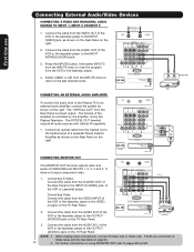
...the VIDEO out jack on the right. / G-LINK Back of VCR AUDIO OUT VIDEO OUT VCR / G-LINK Stereo System Amplifier OPTICAL INPUT CONNECTING MONITOR OUT The MONITOR OUT terminal outputs video and audio of the VCR or Laserdisk player. The OPTICAL OUT terminal outputs all ...or the laserdisc player to the last channel tuned. First time use Connecting External Audio/Video Devices CONNECTING A VIDEO AND MONAURAL AUDIO SOURCE TO INPUT 1, INPUT 2 OR INPUT 5 1. Select CABLE or AIR from the VIDEO OUT of the amplifier is a fixed output. It does not output component video. 1. Connecting...
...the VIDEO out jack on the right. / G-LINK Back of VCR AUDIO OUT VIDEO OUT VCR / G-LINK Stereo System Amplifier OPTICAL INPUT CONNECTING MONITOR OUT The MONITOR OUT terminal outputs video and audio of the VCR or Laserdisk player. The OPTICAL OUT terminal outputs all ...or the laserdisc player to the last channel tuned. First time use Connecting External Audio/Video Devices CONNECTING A VIDEO AND MONAURAL AUDIO SOURCE TO INPUT 1, INPUT 2 OR INPUT 5 1. Select CABLE or AIR from the VIDEO OUT of the amplifier is a fixed output. It does not output component video. 1. Connecting...

Owners Guide
Page 21
...this is equipped with up to 2 external Audio/Video components. You can control up to a total of an AV Network setup between your Hitachi Plasma TV Remote Control. Please see the following example of four external components. 2. CONNECTING EXTERNAL AUDIO/VIDEO COMPONENTS TO IR BLASTER FOR AV... etc.). Video Audio TV Guide On Screen Channel Manager Locks Timers Setup Power Swivel Move SEL Select Setup Menu Preference Screen Saver Set The Inputs Set AV NET Set Closed Captions Set Monitor Out Upgrades Quick Start Up Move SEL Return NOTE: 1. This feature helps to control your...
...this is equipped with up to 2 external Audio/Video components. You can control up to a total of an AV Network setup between your Hitachi Plasma TV Remote Control. Please see the following example of four external components. 2. CONNECTING EXTERNAL AUDIO/VIDEO COMPONENTS TO IR BLASTER FOR AV... etc.). Video Audio TV Guide On Screen Channel Manager Locks Timers Setup Power Swivel Move SEL Select Setup Menu Preference Screen Saver Set The Inputs Set AV NET Set Closed Captions Set Monitor Out Upgrades Quick Start Up Move SEL Return NOTE: 1. This feature helps to control your...

Owners Guide
Page 24
... button while entering your device code to program the remote (see pages 34-41). ቨ ቯ You can also use this button in an optional Input access feature (see page 39). ቪ ቭ ቦ PAUSE button ቮ Press the PAUSE button to cycle through the three different freeze modes (see ቫ...
... button while entering your device code to program the remote (see pages 34-41). ቨ ቯ You can also use this button in an optional Input access feature (see page 39). ቪ ቭ ቦ PAUSE button ቮ Press the PAUSE button to cycle through the three different freeze modes (see ቫ...

Owners Guide
Page 25
...: Please see Appendix C on page 100. • Antenna-Digital (16:9) • HDMI-720p/1080i Input • Component-720p/1080i Input Note: Please see also page 45). 25 However, all five video inputs have independent Aspect Style settings. 2. Depending on conventional (4:3) sources. 16:9 STANDARD Use this aspect mode to ...only 15% of your total viewing time to quickly change the picture format ASPECT ratio. Note: Use this mode for the other ANT input. How to Use the Remote to Control Your TV ቧ ASPECT button Press this button to prevent uneven aging of the phosphors. The...
...: Please see Appendix C on page 100. • Antenna-Digital (16:9) • HDMI-720p/1080i Input • Component-720p/1080i Input Note: Please see also page 45). 25 However, all five video inputs have independent Aspect Style settings. 2. Depending on conventional (4:3) sources. 16:9 STANDARD Use this aspect mode to ...only 15% of your total viewing time to quickly change the picture format ASPECT ratio. Note: Use this mode for the other ANT input. How to Use the Remote to Control Your TV ቧ ASPECT button Press this button to prevent uneven aging of the phosphors. The...

Owners Guide
Page 26
...Day CC Off Closed Caption setting 16:9 Standard 1:00AM Aspect Mode Event Timer. INPUT 1 INPUT 2 Photo Input IEEE 1394 Cable Air Input 1 Move SEL Sel. When an S-VIDEO Input is connected to choose INPUT 3. PHOTO INPUT Select to access your pictures from a Day CC Off 4:3 Expanded digital camera,... USB memory or memory card USB drive connected to When a Component Video: Y-PbPr Input is connected to INPUT 3 INPUT 3 INPUT 4 Select to INPUT 1 YPBPR:1 480i 11:00PM INFO IEEE1394 the Photo Input in the side panel of the (CBL), and (SAT/STB) while in (CBL)(SAT/STB)...
...Day CC Off Closed Caption setting 16:9 Standard 1:00AM Aspect Mode Event Timer. INPUT 1 INPUT 2 Photo Input IEEE 1394 Cable Air Input 1 Move SEL Sel. When an S-VIDEO Input is connected to choose INPUT 3. PHOTO INPUT Select to access your pictures from a Day CC Off 4:3 Expanded digital camera,... USB memory or memory card USB drive connected to When a Component Video: Y-PbPr Input is connected to INPUT 3 INPUT 3 INPUT 4 Select to INPUT 1 YPBPR:1 480i 11:00PM INFO IEEE1394 the Photo Input in the side panel of the (CBL), and (SAT/STB) while in (CBL)(SAT/STB)...

Owners Guide
Page 27
... DVD-RAM disc may not work with low battery power may show Picture Numbers in Thumbnail view, plus other information in this Photo Input. 6. Photo Input IEEE 1394 Cable Air Input 1 Move SEL Sel. 2. Please wait 1 or 2 minutes before checking your photos in individual photos. 4. Press INFO button to ... and select individual chosen photos. Use the CURSOR PAD buttons ̆, ̄, ̇ or ̈ and the SELECT button to show "Input device not detected" if the digital camera's large capacity memory is fully loaded, or because of digital Photos that can be displayed is selected. ...
... DVD-RAM disc may not work with low battery power may show Picture Numbers in Thumbnail view, plus other information in this Photo Input. 6. Photo Input IEEE 1394 Cable Air Input 1 Move SEL Sel. 2. Please wait 1 or 2 minutes before checking your photos in individual photos. 4. Press INFO button to ... and select individual chosen photos. Use the CURSOR PAD buttons ̆, ̄, ̇ or ̈ and the SELECT button to show "Input device not detected" if the digital camera's large capacity memory is fully loaded, or because of digital Photos that can be displayed is selected. ...

Owners Guide
Page 28
... numbers; 5th to read. JPEG format should be 8 characters (Ex. While the Interval sub menu is highlighted, press the SELECT button to select the Photo Input Device Drive when using a USB Drive device. Rotate Slideshow Device Start Interval 30sec DEVICE Select this menu item to start a slideshow of the slideshow. Pictures...
... numbers; 5th to read. JPEG format should be 8 characters (Ex. While the Interval sub menu is highlighted, press the SELECT button to select the Photo Input Device Drive when using a USB Drive device. Rotate Slideshow Device Start Interval 30sec DEVICE Select this menu item to start a slideshow of the slideshow. Pictures...


