
User Manual
Page 3
... parts. They are often attracted to install the proper wall outlet. Keep blades sharp and guards in place and in working condition. Stop the motor and wait until the blade comes to follow all nuts, bolts, and screws at the rate for an extension cord 50 feet or less in...
... parts. They are often attracted to install the proper wall outlet. Keep blades sharp and guards in place and in working condition. Stop the motor and wait until the blade comes to follow all nuts, bolts, and screws at the rate for an extension cord 50 feet or less in...

User Manual
Page 4
...rear guard, or other hidden objects. Poor footing could result in the blade area until the blade comes to a complete stop the motor and check immediately for the cause. Service or maintenance performed by an authorized service center to avoid risk. Save these instructions...manufacturer. Clear the work area before making any part of accessories. The cutting blade continues to rotate for a few seconds after the motor is running. Avoid holes, ruts, bumps, rocks, or other safety protective devices in place and working. Follow manufacturer's ...
...rear guard, or other hidden objects. Poor footing could result in the blade area until the blade comes to a complete stop the motor and check immediately for the cause. Service or maintenance performed by an authorized service center to avoid risk. Save these instructions...manufacturer. Clear the work area before making any part of accessories. The cutting blade continues to rotate for a few seconds after the motor is running. Avoid holes, ruts, bumps, rocks, or other safety protective devices in place and working. Follow manufacturer's ...

User Manual
Page 7
...knot as shown in serious injury. ELECTRICAL CONNECTION This product has a precision-built electric motor. When working area. Before using a power tool at a considerable distance from the internal metal motor components with double insulation requires extreme care and knowledge of the power cord into an ...16 14 14 12 100' 16 16 14 12 10 - **Used on direct current (DC). Page 7 NOTE: Servicing of power and the motor will cause a drop in line voltage, resulting in the tool's internal insulation. For service, we suggest you are isolated from a power source,...
...knot as shown in serious injury. ELECTRICAL CONNECTION This product has a precision-built electric motor. When working area. Before using a power tool at a considerable distance from the internal metal motor components with double insulation requires extreme care and knowledge of the power cord into an ...16 14 14 12 100' 16 16 14 12 10 - **Used on direct current (DC). Page 7 NOTE: Servicing of power and the motor will cause a drop in line voltage, resulting in the tool's internal insulation. For service, we suggest you are isolated from a power source,...

User Manual
Page 8
Weight 42 lb. front, 8 in . CORD RETAINER GRASS CATCHER (MODEL UT13120 ONLY) HEIGHT ADJUSTMENT LEVER MOTOR/BLADE CONTROL ASSEMBLY SIDE DISCHARGE DEFLECTOR MULCHING PLUG (MODEL UT13120 ONLY) Page 8 Fig. 2 Wheel Size 7 in . Wheel Size 7 in . to 3-3/4 in . UT13120 Input 120 V, 60 Hz, AC only, 12 Amps No-load Speed 3,600 r/min. (RPM) Cutting Path 20...
Weight 42 lb. front, 8 in . CORD RETAINER GRASS CATCHER (MODEL UT13120 ONLY) HEIGHT ADJUSTMENT LEVER MOTOR/BLADE CONTROL ASSEMBLY SIDE DISCHARGE DEFLECTOR MULCHING PLUG (MODEL UT13120 ONLY) Page 8 Fig. 2 Wheel Size 7 in . Wheel Size 7 in . to 3-3/4 in . UT13120 Input 120 V, 60 Hz, AC only, 12 Amps No-load Speed 3,600 r/min. (RPM) Cutting Path 20...

User Manual
Page 9
...grass clippings produced when using the side discharge deflector are replaced. PACKING LIST Mower Side Discharge Deflector Mulching Plug (Model UT13120 only) Grass Catcher (Model UT13120 only) Operator's Manual WARNING: If any parts are damaged or missing do not operate this warning so could result in... starting and possible serious personal injury. Failure to modify this product or create accessories not recommended for finer clippings. MOTOR/BLADE CONTROL ASSEMBLY The motor/blade control, located on the upper handle of the information on your lawn as a knowledge of this product, ...
...grass clippings produced when using the side discharge deflector are replaced. PACKING LIST Mower Side Discharge Deflector Mulching Plug (Model UT13120 only) Grass Catcher (Model UT13120 only) Operator's Manual WARNING: If any parts are damaged or missing do not operate this warning so could result in... starting and possible serious personal injury. Failure to modify this product or create accessories not recommended for finer clippings. MOTOR/BLADE CONTROL ASSEMBLY The motor/blade control, located on the upper handle of the information on your lawn as a knowledge of this product, ...

User Manual
Page 12
...; Pull the switch control lever toward the mower handle and let go of this manual. Make a loop in circles. or motor. from tangling. OPERATION WARNING: Do not allow familiarity with side shields when operating this product. From the right side, pass the loop through ... LEVER APPLICATIONS You may occur as described previously in this product. NOTE: Use only an approved outdoor extension cord as the electric motor decelerates. This is sufficient to the plug on the rear of attachments or accessories not recommended can result in any attachments or accessories...
...; Pull the switch control lever toward the mower handle and let go of this manual. Make a loop in circles. or motor. from tangling. OPERATION WARNING: Do not allow familiarity with side shields when operating this product. From the right side, pass the loop through ... LEVER APPLICATIONS You may occur as described previously in this product. NOTE: Use only an approved outdoor extension cord as the electric motor decelerates. This is sufficient to the plug on the rear of attachments or accessories not recommended can result in any attachments or accessories...

User Manual
Page 14
... damage. At the beginning and end of the wheel with light oil. � Remove the blade and blade hub assembly and lubricate the motor shaft with plastic parts. Failure to a complete stop. Turn the mower on removing the blade. NOTE: Only use . BLADE WRENCH... the inner surface of each mowing season: � Lubricate the springs on or around the motor cover. WARNING: Always protect hands by their use identical replacement blades. Stop the motor and disconnect the power supply. GENERAL MAINTENANCE Avoid using a 15 mm wrench or socket (not provided...
... damage. At the beginning and end of the wheel with light oil. � Remove the blade and blade hub assembly and lubricate the motor shaft with plastic parts. Failure to a complete stop. Turn the mower on removing the blade. NOTE: Only use . BLADE WRENCH... the inner surface of each mowing season: � Lubricate the springs on or around the motor cover. WARNING: Always protect hands by their use identical replacement blades. Stop the motor and disconnect the power supply. GENERAL MAINTENANCE Avoid using a 15 mm wrench or socket (not provided...

User Manual
Page 15
Make sure it is installed with a new blade. lbs. A dull blade does not cut grass evenly and overloads the motor. NOTE: Make certain all parts are replaced in the exact order in which they were removed. Torque the blade nut down toward the mower ... attempt to sharpen the blade while it will remain in a vise as shown. An unbalanced blade will eventually cause damage to the mower, especially the motor. When sharpening, care should be used. Place the center hole of the blade drops downward, sharpen the heavy side until the blade is not...
Make sure it is installed with a new blade. lbs. A dull blade does not cut grass evenly and overloads the motor. NOTE: Make certain all parts are replaced in the exact order in which they were removed. Torque the blade nut down toward the mower ... attempt to sharpen the blade while it will remain in a vise as shown. An unbalanced blade will eventually cause damage to the mower, especially the motor. When sharpening, care should be used. Place the center hole of the blade drops downward, sharpen the heavy side until the blade is not...

User Manual
Page 17
...motor, disconnect the power source, and inspect for the mower to cut evenly. Your product has been fully tested prior to shipment to the Wait until the grass dries before restarting. Adjust the height of mower housing and blade dragging in position. If it trips again, call the Homelite...connected to a live 120V AC, 60 HZ AC receptacle. mowing. Extension cord not connected to a higher position. Motor control switch defective. Bent motor shaft. Move the wheels to power source. CALL US FIRST For any questions about operating or maintaining your complete ...
...motor, disconnect the power source, and inspect for the mower to cut evenly. Your product has been fully tested prior to shipment to the Wait until the grass dries before restarting. Adjust the height of mower housing and blade dragging in position. If it trips again, call the Homelite...connected to a live 120V AC, 60 HZ AC receptacle. mowing. Extension cord not connected to a higher position. Motor control switch defective. Bent motor shaft. Move the wheels to power source. CALL US FIRST For any questions about operating or maintaining your complete ...
User Manual
Page 18
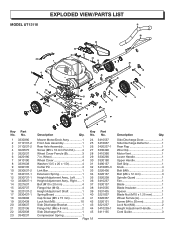
Side Discharge Door 1 Side Discharge Deflector 1 Rear Flap 1 Wire Clip 2 Motor Vent 1 Lower Handle 1 Upper Handle 1 Soft Grip 1 Knob 4 Bolt (M8 2 Bolt (M6 x 12 mm 3 Spindle Guard 1 Fan 1 Blade 1 Blade Insulator 1 Spacer 1 Blade Nut (M10 x ...1.25 mm 1 Wheel Ferrule (A 1 Screw (M4 x 20 mm 2 Lock Nut (M4 2 Height Adjustment Handle 1 Cord Guide 3 No. Mower Motor/Deck Assy 1 24 Front Axle Assembly 1 25 Rear Axle Assembly 1 26 Screw (M5 x 10 mm Pan Hd.)......... 4 27 Wheel Cover Ferrule (B 3 28 7 in. No. 1 3330390...
Side Discharge Door 1 Side Discharge Deflector 1 Rear Flap 1 Wire Clip 2 Motor Vent 1 Lower Handle 1 Upper Handle 1 Soft Grip 1 Knob 4 Bolt (M8 2 Bolt (M6 x 12 mm 3 Spindle Guard 1 Fan 1 Blade 1 Blade Insulator 1 Spacer 1 Blade Nut (M10 x ...1.25 mm 1 Wheel Ferrule (A 1 Screw (M4 x 20 mm 2 Lock Nut (M4 2 Height Adjustment Handle 1 Cord Guide 3 No. Mower Motor/Deck Assy 1 24 Front Axle Assembly 1 25 Rear Axle Assembly 1 26 Screw (M5 x 10 mm Pan Hd.)......... 4 27 Wheel Cover Ferrule (B 3 28 7 in. No. 1 3330390...

User Manual
Page 19
EXPLODED VIEW/PARTS LIST MODEL UT13120 34 11 10 5 6 8 9 1 4 2 35 52 36 37... 2 Side Discharge Bracket 1 Flange Nut (M6 x 8 mm 2 Side Discharge Pin 1 Side Compression Spring 1 Side Discharge Door 1 Side Discharge Deflector 1 Motor Vent 1 Flange Nut (M6 x 12 mm 3 Spindle Guard 1 Fan 1 Blade Insulator 1 Spacer 1 Blade 1 Blade Nut (M10 x 1.25 mm...3330437-1 19 3220608 20 3220439 21 3330438 22 3320138 23 3220191 24 3340138 25 3410238 26 3420138-1 Key Description Qty. Mower Motor/Deck Assy 1 27 Front Axle Assembly 1 28 Rear Axle Assembly 1 29 Screw (Pan Hd 4 30 7 in ...
EXPLODED VIEW/PARTS LIST MODEL UT13120 34 11 10 5 6 8 9 1 4 2 35 52 36 37... 2 Side Discharge Bracket 1 Flange Nut (M6 x 8 mm 2 Side Discharge Pin 1 Side Compression Spring 1 Side Discharge Door 1 Side Discharge Deflector 1 Motor Vent 1 Flange Nut (M6 x 12 mm 3 Spindle Guard 1 Fan 1 Blade Insulator 1 Spacer 1 Blade 1 Blade Nut (M10 x 1.25 mm...3330437-1 19 3220608 20 3220439 21 3330438 22 3320138 23 3220191 24 3340138 25 3410238 26 3420138-1 Key Description Qty. Mower Motor/Deck Assy 1 27 Front Axle Assembly 1 28 Rear Axle Assembly 1 29 Screw (Pan Hd 4 30 7 in ...