

Owner's Manual
Page 1
... No * CT87A is right for your system, visit www.honeywell.com/ yourhome or call Honeywell Customer Care at 1-800-468-1502. Registered Trademark Copyright © 2002 Honeywell All Rights Reserved 69-0274-6 Installation Instructions Compatible with: Heating/Cooling system CT87A CT87B CT87J Heating only... heating/cooling unit No (compressor) with auxiliary or backup heat. CT87A,B,J Round® Thermostat LOW VOLTAGE (15 TO 30 VAC), THERMOSTAT AND MOUNTING HARDWARE 1 Verify that you have the correct thermostat Using the compatibility chart below, verify that you are unsure which ...
... No * CT87A is right for your system, visit www.honeywell.com/ yourhome or call Honeywell Customer Care at 1-800-468-1502. Registered Trademark Copyright © 2002 Honeywell All Rights Reserved 69-0274-6 Installation Instructions Compatible with: Heating/Cooling system CT87A CT87B CT87J Heating only... heating/cooling unit No (compressor) with auxiliary or backup heat. CT87A,B,J Round® Thermostat LOW VOLTAGE (15 TO 30 VAC), THERMOSTAT AND MOUNTING HARDWARE 1 Verify that you have the correct thermostat Using the compatibility chart below, verify that you are unsure which ...
Owner's Manual
Page 2
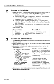
... Current setting: If you cannot find the heat LEVER anticipator setting on the old thermostat, you can be used to the heating/cooling system at the main fuse/circuit breaker panel. 2. round head screws • Wallplate (CT87A) or subbase (CT87B, CT87J) • Cover ring (select models only). Necessary if installing on the wall; Optional...
... Current setting: If you cannot find the heat LEVER anticipator setting on the old thermostat, you can be used to the heating/cooling system at the main fuse/circuit breaker panel. 2. round head screws • Wallplate (CT87A) or subbase (CT87B, CT87J) • Cover ring (select models only). Necessary if installing on the wall; Optional...

Owner's Manual
Page 3
... on the wall Refer to keep them around a pencil to Fig. 4 as you work. Disconnect the wires from the old thermostat and wrap them from falling back into the wall (Fig. 3). WIRES THROUGH WALL OPENING If this control, or of an old...Do not label the wires by color. 6. M19086 MERCURY NOTICE Fig. 3. Fig. 2. Wrapping wires. CT87A,B,J ROUND® THERMOSTAT 5. Labeling wires. COVER RING WALLPLATE NO. 4 X 1 INCH SHEET METAL SCREWS (2) 3 THERMOSTAT WIRING OPENING M20188 69-0274-6 Installing wallplate/subbase on the old thermo- Label the wires using the letter...
... on the wall Refer to keep them around a pencil to Fig. 4 as you work. Disconnect the wires from the old thermostat and wrap them from falling back into the wall (Fig. 3). WIRES THROUGH WALL OPENING If this control, or of an old...Do not label the wires by color. 6. M19086 MERCURY NOTICE Fig. 3. Fig. 2. Wrapping wires. CT87A,B,J ROUND® THERMOSTAT 5. Labeling wires. COVER RING WALLPLATE NO. 4 X 1 INCH SHEET METAL SCREWS (2) 3 THERMOSTAT WIRING OPENING M20188 69-0274-6 Installing wallplate/subbase on the old thermo- Label the wires using the letter...

Owner's Manual
Page 4
...sides of the wallplate/subbase align with the screw holes on top. • If attaching subbase directly to Fig. 5 as you marked. 5. CT87A,B,J ROUND® THERMOSTAT 1. Position the wallplate or subbase. • If using the cover ring: Position the cover ring against the wall so that the fan and heating... the UP indicator on the top. 3. If installing on an outlet box Refer to the wall: Position so that the arrow in . ROUND HEAD SCREW (2) A THERMOSTAT WIRING HOLE 1 THE TWO INNER HOLES ARE USED WITH WALLPLATE. 2 IF OUTLET BOX IS HORIZONTAL, MOUNT COVER RING IN POSITION SHOWN, BUT...
...sides of the wallplate/subbase align with the screw holes on top. • If attaching subbase directly to Fig. 5 as you marked. 5. CT87A,B,J ROUND® THERMOSTAT 1. Position the wallplate or subbase. • If using the cover ring: Position the cover ring against the wall so that the fan and heating... the UP indicator on the top. 3. If installing on an outlet box Refer to the wall: Position so that the arrow in . ROUND HEAD SCREW (2) A THERMOSTAT WIRING HOLE 1 THE TWO INNER HOLES ARE USED WITH WALLPLATE. 2 IF OUTLET BOX IS HORIZONTAL, MOUNT COVER RING IN POSITION SHOWN, BUT...

Owner's Manual
Page 5
Fig. 6. SPIRIT LEVEL LEVELING POSTS (2) OPENING FOR THERMOSTAT WIRING MOUNTING SLOTS M3319A 2. screws. 4. Leveling the wallplate. Place the cover ring against the outlet box so that the arrow in the middle of the .... 1. Rotate the wallplate/subbase until level as shown in . To level the subbase, use the leveling posts directly below the Heat and Fan indicators. CT87A,B,J ROUND® THERMOSTAT 1. Pull the wires through the wiring hole on the left side of the wallplate/subbase. 5 Level the wallplate or subbase IMPORTANT: The wallplate/subbase must...
Fig. 6. SPIRIT LEVEL LEVELING POSTS (2) OPENING FOR THERMOSTAT WIRING MOUNTING SLOTS M3319A 2. screws. 4. Leveling the wallplate. Place the cover ring against the outlet box so that the arrow in the middle of the .... 1. Rotate the wallplate/subbase until level as shown in . To level the subbase, use the leveling posts directly below the Heat and Fan indicators. CT87A,B,J ROUND® THERMOSTAT 1. Pull the wires through the wiring hole on the left side of the wallplate/subbase. 5 Level the wallplate or subbase IMPORTANT: The wallplate/subbase must...

Owner's Manual
Page 6
...any excess wire back into the wall. 69-0274-6 6 CT87A,B,J ROUND® THERMOSTAT 6 Wire the thermostat 1. FOR STRAIGHT CONNECTION- STRIP 7/16 in . [8 mm] FOR WRAPAROUND CONNECTION- Loosen the terminal screws and slip each old thermostat wire with its matching terminal. 4. See Fig. 8 through... 13 wiring diagrams. Wiring Cross-reference Wire Label R, RH, 4, V Rc, R W, W1, H Y, Y1, M G, F B O See Fig. 13 Connect to CT87A R W Y See Fig. 9 Connect to Connect to CT87B CT87J RH R Rc ...
...any excess wire back into the wall. 69-0274-6 6 CT87A,B,J ROUND® THERMOSTAT 6 Wire the thermostat 1. FOR STRAIGHT CONNECTION- STRIP 7/16 in . [8 mm] FOR WRAPAROUND CONNECTION- Loosen the terminal screws and slip each old thermostat wire with its matching terminal. 4. See Fig. 8 through... 13 wiring diagrams. Wiring Cross-reference Wire Label R, RH, 4, V Rc, R W, W1, H Y, Y1, M G, F B O See Fig. 13 Connect to CT87A R W Y See Fig. 9 Connect to Connect to CT87B CT87J RH R Rc ...
Owner's Manual
Page 7
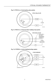
CT87A WALLPLATE R Y W POWER HEAT TO SYSTEM M20183 Fig. 9. CT87B for a 3-wire hot water heating only system. COOL • OFF • HEAT FAN ON RH G RC Y W AUTO • CT87B SUBBASE POWER FAN COOL TO SYSTEM HEAT JUMPER RH TO RC M20185 7 69-0274-6 CT87A for a 4-wire heating/cooling system. CT87A for a 2-wire heating only system. CT87A,B,J ROUND® THERMOSTAT Fig. 8. R Y W CT87A WALLPLATE WIRE LABELS (LETTERS ON ORIGINAL THERMOSTAT TERMINALS) R 3-WIRE W HOT WATER ZONE VALVE B M20184 Fig. 10.
CT87A WALLPLATE R Y W POWER HEAT TO SYSTEM M20183 Fig. 9. CT87B for a 3-wire hot water heating only system. COOL • OFF • HEAT FAN ON RH G RC Y W AUTO • CT87B SUBBASE POWER FAN COOL TO SYSTEM HEAT JUMPER RH TO RC M20185 7 69-0274-6 CT87A for a 4-wire heating/cooling system. CT87A for a 2-wire heating only system. CT87A,B,J ROUND® THERMOSTAT Fig. 8. R Y W CT87A WALLPLATE WIRE LABELS (LETTERS ON ORIGINAL THERMOSTAT TERMINALS) R 3-WIRE W HOT WATER ZONE VALVE B M20184 Fig. 10.

Owner's Manual
Page 8
... ATTACHED TO Y OR W, AND P ON YOUR OLD THERMOSTAT, CONTACT YOUR LOCAL CONTRACTOR FOR FURTHER ASSISTANCE. COOL • OFF • HEAT FAN ON RH G RC Y W AUTO • CT87B SUBBASE HEATING POWER FAN TO SYSTEM COOLING POWER TO SYSTEM COOL HEAT Fig. 12. M20228 69-0274-6 8 CT87B for a 5-wire heating/cooling system. CT87A,B,J ROUND® THERMOSTAT Fig. 11.
... ATTACHED TO Y OR W, AND P ON YOUR OLD THERMOSTAT, CONTACT YOUR LOCAL CONTRACTOR FOR FURTHER ASSISTANCE. COOL • OFF • HEAT FAN ON RH G RC Y W AUTO • CT87B SUBBASE HEATING POWER FAN TO SYSTEM COOLING POWER TO SYSTEM COOL HEAT Fig. 12. M20228 69-0274-6 8 CT87B for a 5-wire heating/cooling system. CT87A,B,J ROUND® THERMOSTAT Fig. 11.

Owner's Manual
Page 9
... the wallplate or subbase so that holds the mercury switch in Fig. 14. Pull off the thermostat cover and discard the red plastic insert that the three captive mounting screws align with the three raised ... SCALE .12 .10 M20226 3. Tightening mounting screws. Tighten the three captive mounting screws as shown in place during shipping. 2. CT87A,B,J ROUND® THERMOSTAT 7 Mount the thermostat 1. IMPORTANT: This prevents the thermostat from being damaged. CAPTIVE SCREWS (3) M20227 9 69-0274-6 Adjusting heat anticipator indicator. Fig. 14. Fig. 15. NOTE: ...
... the wallplate or subbase so that holds the mercury switch in Fig. 14. Pull off the thermostat cover and discard the red plastic insert that the three captive mounting screws align with the three raised ... SCALE .12 .10 M20226 3. Tightening mounting screws. Tighten the three captive mounting screws as shown in place during shipping. 2. CT87A,B,J ROUND® THERMOSTAT 7 Mount the thermostat 1. IMPORTANT: This prevents the thermostat from being damaged. CAPTIVE SCREWS (3) M20227 9 69-0274-6 Adjusting heat anticipator indicator. Fig. 14. Fig. 15. NOTE: ...

Owner's Manual
Page 10
... High-efficiency warm air Standard warm air Electric heat Heat anticipator setting: 1.2 0.8 0.8 0.4 0.3 2. Turn the dial until the temperature on the thermostat cover. If you recorded in the table below .3 ampere. 9 Check heating/cooling operation Check heating 1. SETTING SCALE 69-0274-6 THERMOMETER 10 M9656 ... system should stop. If the furnace shuts off before the set the system switch to maintain accurate temperature control. 1. CT87A,B,J ROUND® THERMOSTAT 8 Set the heat anticipator for your type of system shown in Step 3, sub-step 3. Fig. 16.
... High-efficiency warm air Standard warm air Electric heat Heat anticipator setting: 1.2 0.8 0.8 0.4 0.3 2. Turn the dial until the temperature on the thermostat cover. If you recorded in the table below .3 ampere. 9 Check heating/cooling operation Check heating 1. SETTING SCALE 69-0274-6 THERMOMETER 10 M9656 ... system should stop. If the furnace shuts off before the set the system switch to maintain accurate temperature control. 1. CT87A,B,J ROUND® THERMOSTAT 8 Set the heat anticipator for your type of system shown in Step 3, sub-step 3. Fig. 16.

Owner's Manual
Page 11
... switch on the left to Cool on the top setting scale aligns with the heating or cooling system. 11 69-0274-6 CT87A,B,J ROUND® THERMOSTAT Check cooling IMPORTANT: To avoid damaging the compressor in the air conditioner, do not operate the cooling system when the outdoor temperature... below 50°F (10°C). 1. Both the heating and cooling systems are off. The fan runs continuously. CT87B, J switches Switch System Fan Setting Result Cool Off The thermostat controls your CT87 has a subbase, set the temperature, turn the dial until the pointer on the CT87J model. ...
... switch on the left to Cool on the top setting scale aligns with the heating or cooling system. 11 69-0274-6 CT87A,B,J ROUND® THERMOSTAT Check cooling IMPORTANT: To avoid damaging the compressor in the air conditioner, do not operate the cooling system when the outdoor temperature... below 50°F (10°C). 1. Both the heating and cooling systems are off. The fan runs continuously. CT87B, J switches Switch System Fan Setting Result Cool Off The thermostat controls your CT87 has a subbase, set the temperature, turn the dial until the pointer on the CT87J model. ...

Owner's Manual
Page 12
... implied warranty lasts, so the above . Some states do not allow limitations on recycled paper containing at Honeywell's option) within the terms stated above limitation may not apply to you . CT87A,B,J ROUND® THERMOSTAT Limited One-Year Warranty Honeywell warrants this product, excluding battery, to be to repair or replace the product within a reasonable period...
... implied warranty lasts, so the above . Some states do not allow limitations on recycled paper containing at Honeywell's option) within the terms stated above limitation may not apply to you . CT87A,B,J ROUND® THERMOSTAT Limited One-Year Warranty Honeywell warrants this product, excluding battery, to be to repair or replace the product within a reasonable period...

