

Owner's Manual
Page 1
...No No * CT87A is right for your system, visit www.honeywell.com/ yourhome or call Honeywell Customer Care at 1-800-468-1502. No Yes Electric heat ... (compressor) with no auxiliary or backup heat. Installation Instructions Compatible with: Heating/Cooling system CT87A CT87B CT87J Heating only: Gas or oil fueled warm air, steam, or hot Yes water heat Yes...with auxiliary or backup heat. CT87A,B,J Round® Thermostat LOW VOLTAGE (15 TO 30 VAC), THERMOSTAT AND MOUNTING HARDWARE 1 Verify that you have the correct thermostat Using the compatibility chart below, verify that you are...
...No No * CT87A is right for your system, visit www.honeywell.com/ yourhome or call Honeywell Customer Care at 1-800-468-1502. No Yes Electric heat ... (compressor) with no auxiliary or backup heat. Installation Instructions Compatible with: Heating/Cooling system CT87A CT87B CT87J Heating only: Gas or oil fueled warm air, steam, or hot Yes water heat Yes...with auxiliary or backup heat. CT87A,B,J Round® Thermostat LOW VOLTAGE (15 TO 30 VAC), THERMOSTAT AND MOUNTING HARDWARE 1 Verify that you have the correct thermostat Using the compatibility chart below, verify that you are...
Owner's Manual
Page 2
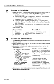
.... 2. can use a TYPICAL LOCATION OF A standard setting for installation 1. Fig. 1. Unscrew and remove the old thermostat wallplate from the wall, but do not disconnect the wires. 69-0274-6 2 round head screws • Wallplate (CT87A) or subbase (CT87B, CT87J) • Cover ring (select models only). You may affect its accuracy. CT87A,B,J ROUND®...
.... 2. can use a TYPICAL LOCATION OF A standard setting for installation 1. Fig. 1. Unscrew and remove the old thermostat wallplate from the wall, but do not disconnect the wires. 69-0274-6 2 round head screws • Wallplate (CT87A) or subbase (CT87B, CT87J) • Cover ring (select models only). You may affect its accuracy. CT87A,B,J ROUND®...

Owner's Manual
Page 3
... waste management authority for instructions regarding recycling and the proper disposal of this thermostat is replacing a control that came with the CT87. COVER RING WALLPLATE NO. 4 X 1 INCH SHEET METAL SCREWS (2) 3 THERMOSTAT WIRING OPENING M20188 69-0274-6 Wrapping wires. Installing wallplate/subbase on the wall...around a pencil to Fig. 4 as you work. Do not label the wires by color. 6. Labeling wires. CT87A,B,J ROUND® THERMOSTAT 5. M19086 MERCURY NOTICE Fig. 3. WIRES THROUGH WALL OPENING If this control, or of the terminal on the old thermo- Identify each wire...
... waste management authority for instructions regarding recycling and the proper disposal of this thermostat is replacing a control that came with the CT87. COVER RING WALLPLATE NO. 4 X 1 INCH SHEET METAL SCREWS (2) 3 THERMOSTAT WIRING OPENING M20188 69-0274-6 Wrapping wires. Installing wallplate/subbase on the wall...around a pencil to Fig. 4 as you work. Do not label the wires by color. 6. Labeling wires. CT87A,B,J ROUND® THERMOSTAT 5. M19086 MERCURY NOTICE Fig. 3. WIRES THROUGH WALL OPENING If this control, or of the terminal on the old thermo- Identify each wire...

Owner's Manual
Page 4
... the wallplate/subbase and cover ring, and drill two 1/16-in the middle of the wallplate or subbase. 4. ROUND HEAD SCREW (2) A THERMOSTAT WIRING HOLE 1 THE TWO INNER HOLES ARE USED WITH WALLPLATE. 2 IF OUTLET BOX IS HORIZONTAL, MOUNT COVER RING IN POSITION SHOWN, BUT ... wallplate or subbase. • If using the cover ring: Position the cover ring against the wall so that the arrow in . CT87A,B,J ROUND® THERMOSTAT 1. Fig. 5. If installing on the wallplate is pointing up. 2. Rotate the wallplate/subbase until the wiring openings are on an outlet box (subbase shown...
... the wallplate/subbase and cover ring, and drill two 1/16-in the middle of the wallplate or subbase. 4. ROUND HEAD SCREW (2) A THERMOSTAT WIRING HOLE 1 THE TWO INNER HOLES ARE USED WITH WALLPLATE. 2 IF OUTLET BOX IS HORIZONTAL, MOUNT COVER RING IN POSITION SHOWN, BUT ... wallplate or subbase. • If using the cover ring: Position the cover ring against the wall so that the arrow in . CT87A,B,J ROUND® THERMOSTAT 1. Fig. 5. If installing on the wallplate is pointing up. 2. Rotate the wallplate/subbase until the wiring openings are on an outlet box (subbase shown...

Owner's Manual
Page 5
Loosely attach the wallplate/subbase to the cover ring with two 1/2-in. rate thermostat temperature. 1. Tighten the mounting screws after making sure that the wallplate or subbase is pointing up , and pull the wires through. 5. screws. 4. Place the cover .... Leveling the wallplate. Fig. 6. Align the screw slots on the bottom left and right sides of the cover ring. 3. SPIRIT LEVEL LEVELING POSTS (2) OPENING FOR THERMOSTAT WIRING MOUNTING SLOTS M3319A 2. screws, through the wiring hole on the cover ring with the outlet box screw holes, and attach the cover ring to...
Loosely attach the wallplate/subbase to the cover ring with two 1/2-in. rate thermostat temperature. 1. Tighten the mounting screws after making sure that the wallplate or subbase is pointing up , and pull the wires through. 5. screws. 4. Place the cover .... Leveling the wallplate. Fig. 6. Align the screw slots on the bottom left and right sides of the cover ring. 3. SPIRIT LEVEL LEVELING POSTS (2) OPENING FOR THERMOSTAT WIRING MOUNTING SLOTS M3319A 2. screws, through the wiring hole on the cover ring with the outlet box screw holes, and attach the cover ring to...

Owner's Manual
Page 6
CT87A,B,J ROUND® THERMOSTAT 6 Wire the thermostat 1. STRIP 7/16 in . [8 mm] FOR WRAPAROUND CONNECTION- Use the wiring cross-reference table below to match each wire beneath its corresponding terminal on...through 13 wiring diagrams. Wiring Cross-reference Wire Label R, RH, 4, V Rc, R W, W1, H Y, Y1, M G, F B O See Fig. 13 Connect to CT87A R W Y See Fig. 9 Connect to Connect to CT87B CT87J RH R Rc W W Y Y G G B* O* P *Never attach wires to fit the wires underneath the terminal screws (Fig. 7). STRIP 5/16 in . [11 mm] BARRIER M1279 3. Fitting wires under...
CT87A,B,J ROUND® THERMOSTAT 6 Wire the thermostat 1. STRIP 7/16 in . [8 mm] FOR WRAPAROUND CONNECTION- Use the wiring cross-reference table below to match each wire beneath its corresponding terminal on...through 13 wiring diagrams. Wiring Cross-reference Wire Label R, RH, 4, V Rc, R W, W1, H Y, Y1, M G, F B O See Fig. 13 Connect to CT87A R W Y See Fig. 9 Connect to Connect to CT87B CT87J RH R Rc W W Y Y G G B* O* P *Never attach wires to fit the wires underneath the terminal screws (Fig. 7). STRIP 5/16 in . [11 mm] BARRIER M1279 3. Fitting wires under...
Owner's Manual
Page 7
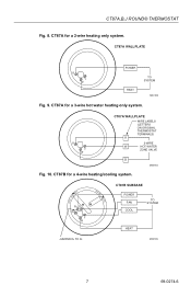
CT87A WALLPLATE R Y W POWER HEAT TO SYSTEM M20183 Fig. 9. R Y W CT87A WALLPLATE WIRE LABELS (LETTERS ON ORIGINAL THERMOSTAT TERMINALS) R 3-WIRE W HOT WATER ZONE VALVE B M20184 Fig. 10. CT87A for a 3-wire hot water heating only system. CT87A for a 2-wire heating only system. CT87B for a 4-wire heating/cooling system. CT87A,B,J ROUND® THERMOSTAT Fig. 8. COOL • OFF • HEAT FAN ON RH G RC Y W AUTO • CT87B SUBBASE POWER FAN COOL TO SYSTEM HEAT JUMPER RH TO RC M20185 7 69-0274-6
CT87A WALLPLATE R Y W POWER HEAT TO SYSTEM M20183 Fig. 9. R Y W CT87A WALLPLATE WIRE LABELS (LETTERS ON ORIGINAL THERMOSTAT TERMINALS) R 3-WIRE W HOT WATER ZONE VALVE B M20184 Fig. 10. CT87A for a 3-wire hot water heating only system. CT87A for a 2-wire heating only system. CT87B for a 4-wire heating/cooling system. CT87A,B,J ROUND® THERMOSTAT Fig. 8. COOL • OFF • HEAT FAN ON RH G RC Y W AUTO • CT87B SUBBASE POWER FAN COOL TO SYSTEM HEAT JUMPER RH TO RC M20185 7 69-0274-6

Owner's Manual
Page 8
COOL • OFF • HEAT FAN ON RH G RC Y W AUTO • CT87B SUBBASE HEATING POWER FAN TO SYSTEM COOLING POWER TO SYSTEM COOL HEAT Fig. 12. CT87J for a 5-wire heating/cooling system. CT87J SUBBASE HEAT FAN ... COMPRESSOR DO NOT ATTACH WIRES TO BOTH B AND O 1 IF WIRES ARE ATTACHED TO Y OR W, AND P ON YOUR OLD THERMOSTAT, CONTACT YOUR LOCAL CONTRACTOR FOR FURTHER ASSISTANCE. M20228 69-0274-6 8 CT87A,B,J ROUND® THERMOSTAT Fig. 11. CT87B for a 4-wire single stage heat pump. M20225 COOL • OFF • HEAT FAN ON WG Y P R B O JUMPER W ...
COOL • OFF • HEAT FAN ON RH G RC Y W AUTO • CT87B SUBBASE HEATING POWER FAN TO SYSTEM COOLING POWER TO SYSTEM COOL HEAT Fig. 12. CT87J for a 5-wire heating/cooling system. CT87J SUBBASE HEAT FAN ... COMPRESSOR DO NOT ATTACH WIRES TO BOTH B AND O 1 IF WIRES ARE ATTACHED TO Y OR W, AND P ON YOUR OLD THERMOSTAT, CONTACT YOUR LOCAL CONTRACTOR FOR FURTHER ASSISTANCE. M20228 69-0274-6 8 CT87A,B,J ROUND® THERMOSTAT Fig. 11. CT87B for a 4-wire single stage heat pump. M20225 COOL • OFF • HEAT FAN ON WG Y P R B O JUMPER W ...

Owner's Manual
Page 9
Fig. 14. Tighten the three captive mounting screws as shown in Fig. 14. Tightening mounting screws. Pull off the thermostat cover and discard the red plastic insert that the three captive mounting screws align with the three raised screw holes on the scale as shown ...in place during shipping. 2. NOTE: These screws complete the installation of the thermostat. Using a pencil point, slide the heat anticipator indicator to 1.2 on the wallplate/subbase. 4. Adjusting heat anticipator indicator. Place the...
Fig. 14. Tighten the three captive mounting screws as shown in Fig. 14. Tightening mounting screws. Pull off the thermostat cover and discard the red plastic insert that the three captive mounting screws align with the three raised screw holes on the scale as shown ...in place during shipping. 2. NOTE: These screws complete the installation of the thermostat. Using a pencil point, slide the heat anticipator indicator to 1.2 on the wallplate/subbase. 4. Adjusting heat anticipator indicator. Place the...

Owner's Manual
Page 10
...transparent dial to the farthest point left. 2. SETTING SCALE 69-0274-6 THERMOMETER 10 M9656 Turn the dial until the temperature on the old thermostat, use the setting for your CT87 has a subbase, set temperature, move the heat anticipator pointer to the number that you could not find...by .1 ampere. Turn the dial until the temperature on the setting scale is below the room temperature that is shown on the thermostat cover. CT87A,B,J ROUND® THERMOSTAT 8 Set the heat anticipator for your type of system shown in Step 3, sub-step 3. If you recorded in the table below...
...transparent dial to the farthest point left. 2. SETTING SCALE 69-0274-6 THERMOMETER 10 M9656 Turn the dial until the temperature on the old thermostat, use the setting for your CT87 has a subbase, set temperature, move the heat anticipator pointer to the number that you could not find...by .1 ampere. Turn the dial until the temperature on the setting scale is below the room temperature that is shown on the thermostat cover. CT87A,B,J ROUND® THERMOSTAT 8 Set the heat anticipator for your type of system shown in Step 3, sub-step 3. If you recorded in the table below...

Owner's Manual
Page 11
CT87B, J switches Switch System Fan Setting Result Cool Off The thermostat controls your heating system. The fan runs continuously. The cooling system should stop. If your CT87 has a subbase, set the temperature, turn the dial until ... the System switch on the CT87J model. 2. Both the heating and cooling systems are off. IMPORTANT: After heating is below room temperature. CT87A,B,J ROUND® THERMOSTAT Check cooling IMPORTANT: To avoid damaging the compressor in the air conditioner, do not operate the cooling system when the outdoor temperature is tested, wait...
CT87B, J switches Switch System Fan Setting Result Cool Off The thermostat controls your heating system. The fan runs continuously. The cooling system should stop. If your CT87 has a subbase, set the temperature, turn the dial until ... the System switch on the CT87J model. 2. Both the heating and cooling systems are off. IMPORTANT: After heating is below room temperature. CT87A,B,J ROUND® THERMOSTAT Check cooling IMPORTANT: To avoid damaging the compressor in the air conditioner, do not operate the cooling system when the outdoor temperature is tested, wait...

Owner's Manual
Page 12
...allow the exclusion or limitation of a consumer. MN10-3860 1985 Douglas Drive North Golden Valley, MN 55422-3992 Honeywell Canada: Honeywell Limited/Honeywell Limitée 35 Dynamic Drive Scarborough, Ontario M1V 4Z9 This warranty does not cover removal or reinstallation costs....purchase, to the retailer where you . CT87A,B,J ROUND® THERMOSTAT Limited One-Year Warranty Honeywell warrants this product, excluding battery, to state. If, at any questions concerning this warranty, please write Honeywell Customer Care, Honeywell Inc., 1985 Douglas Dr. N., Golden Valley, MN 55422-...
...allow the exclusion or limitation of a consumer. MN10-3860 1985 Douglas Drive North Golden Valley, MN 55422-3992 Honeywell Canada: Honeywell Limited/Honeywell Limitée 35 Dynamic Drive Scarborough, Ontario M1V 4Z9 This warranty does not cover removal or reinstallation costs....purchase, to the retailer where you . CT87A,B,J ROUND® THERMOSTAT Limited One-Year Warranty Honeywell warrants this product, excluding battery, to state. If, at any questions concerning this warranty, please write Honeywell Customer Care, Honeywell Inc., 1985 Douglas Dr. N., Golden Valley, MN 55422-...


