
Installation Guide
Page 3
... ...8 3.5 Suppressors ...8 4.0 Installation...9 4.1 Cabinet Mounting ...10 4.2 Reader Wiring...14 4.3 Supervised Input Wiring 14 4.4 NX4S1 Control Output Wiring 16 4.5 Communications ...16 RS-232 Communications 16 RS-485 Communications 18 Ethernet TCP/IP Communications 19 4.6 DIP Switch Settings ...21 4.7 Jumper Settings...23 4.8 Downstream I/O...23 NetAXS Access Control Unit NX4S1 Installation Guide, Document 800-00008, Revision A iii
... ...8 3.5 Suppressors ...8 4.0 Installation...9 4.1 Cabinet Mounting ...10 4.2 Reader Wiring...14 4.3 Supervised Input Wiring 14 4.4 NX4S1 Control Output Wiring 16 4.5 Communications ...16 RS-232 Communications 16 RS-485 Communications 18 Ethernet TCP/IP Communications 19 4.6 DIP Switch Settings ...21 4.7 Jumper Settings...23 4.8 Downstream I/O...23 NetAXS Access Control Unit NX4S1 Installation Guide, Document 800-00008, Revision A iii
Installation Guide
Page 4
...40 5.15 NetAXS™/NetAXS™ Access Controller Panel Connection Detail 41 6.0 NetAXS™ Startup ...42 6.1 LED Operation...42 7.0 Hardware Specifications ...44 7.1 Relay Contacts ...44 7.2 Reader Interface ...44 7.3 NX4S1 Wire Requirements... 44 7.4 Maximum Output Loading 44 7.5 Common Connections 45 7.6 Mechanical...45 7.7 Environment...45 7.8 Communications and Wiring 46 7.9 Reader Wiring...46 7.10 NX4S1 Wiring Diagram 47 8.0 Maintenance...48 9.0 Troubleshooting ...48 10.0 Technical Support...49 10.1 Normal Support Hours 49 10.2 Web ...49 iv www.honeywell...
...40 5.15 NetAXS™/NetAXS™ Access Controller Panel Connection Detail 41 6.0 NetAXS™ Startup ...42 6.1 LED Operation...42 7.0 Hardware Specifications ...44 7.1 Relay Contacts ...44 7.2 Reader Interface ...44 7.3 NX4S1 Wire Requirements... 44 7.4 Maximum Output Loading 44 7.5 Common Connections 45 7.6 Mechanical...45 7.7 Environment...45 7.8 Communications and Wiring 46 7.9 Reader Wiring...46 7.10 NX4S1 Wiring Diagram 47 8.0 Maintenance...48 9.0 Troubleshooting ...48 10.0 Technical Support...49 10.1 Normal Support Hours 49 10.2 Web ...49 iv www.honeywell...

Installation Guide
Page 5
...Card Read / Door Lock Operation 51 A.1.2 Door Egress / Door Lock / Door Status Operation 51 A.2 Standalone Settings...52 A.2.1 NetAXS™ Panel Hardware Settings 52 A.2.2 Communication Settings 52 A.2.3 Emulation Settings ...52 A.2.4 Verifying Communications 52 A.3 Standalone Commands...53 A.3.1 ...A.3.5 C (Card Delete) Command 56 A.3.6 W (Input) Command 57 A.3.7 P (Interlock) Command 57 A.3.8 Flow Control Disable/Enable 58 A.4 NetAXS™ Panel Defaults ...59 A.4.1 Reader Ports ...59 A.4.2 Reader LED Outputs 59 A.4.3 Reader Tamper Inputs 60 A.4.4 Door Egress Inputs...60 A.4.5 ...
...Card Read / Door Lock Operation 51 A.1.2 Door Egress / Door Lock / Door Status Operation 51 A.2 Standalone Settings...52 A.2.1 NetAXS™ Panel Hardware Settings 52 A.2.2 Communication Settings 52 A.2.3 Emulation Settings ...52 A.2.4 Verifying Communications 52 A.3 Standalone Commands...53 A.3.1 ...A.3.5 C (Card Delete) Command 56 A.3.6 W (Input) Command 57 A.3.7 P (Interlock) Command 57 A.3.8 Flow Control Disable/Enable 58 A.4 NetAXS™ Panel Defaults ...59 A.4.1 Reader Ports ...59 A.4.2 Reader LED Outputs 59 A.4.3 Reader Tamper Inputs 60 A.4.4 Door Egress Inputs...60 A.4.5 ...

Installation Guide
Page 7
LIST OF FIGURES Figure 1: NX4S1 Panel Components 6 Figure 2: NetAXS™ NX4S1 Panel Cabinet, Front View 10 Figure 3: NetAXS™ NX4S1 Panel Cabinet, Top View 11 Figure 4: NetAXS™ NX4S1 Panel Cabinet, Bottom View 11 Figure 5: NetAXS™ Panel Cabinet, Left View 12 Figure 6: NetAXS™ NX4S1Panel Cabinet, Right View 13 Figure...232 Configuration 17 Figure 10: RS-485 Configuration via N-485-PCI-2 or PCI-3 18 Figure 11: RS-485 Configuration via NetAXS™ Gateway 19 Figure 12: Ethernet TCP/IP Configuration 19 Figure 13: Ethernet MAC Address Location 20 Figure 14: DIP ...
LIST OF FIGURES Figure 1: NX4S1 Panel Components 6 Figure 2: NetAXS™ NX4S1 Panel Cabinet, Front View 10 Figure 3: NetAXS™ NX4S1 Panel Cabinet, Top View 11 Figure 4: NetAXS™ NX4S1 Panel Cabinet, Bottom View 11 Figure 5: NetAXS™ Panel Cabinet, Left View 12 Figure 6: NetAXS™ NX4S1Panel Cabinet, Right View 13 Figure...232 Configuration 17 Figure 10: RS-485 Configuration via N-485-PCI-2 or PCI-3 18 Figure 11: RS-485 Configuration via NetAXS™ Gateway 19 Figure 12: Ethernet TCP/IP Configuration 19 Figure 13: Ethernet MAC Address Location 20 Figure 14: DIP ...

Installation Guide
Page 9
LIST OF TABLES Table 1 Reader Wiring ...14 Table 2 Default Supervised Input Assignments 14 Table 3 DIP Switch Settings ...22 Table 4 MIRO 32/0 DIP Switch and Jumper Settings 23 Table 5 LED Status ...43 Table 6 Communications and Wiring 46 Table 7 Reader Wiring ...46 Table 8 Troubleshooting Problems and Solutions 48 NetAXS Access Control Unit NX4S1 Installation Guide, Document 800-00008, Revision A ix
LIST OF TABLES Table 1 Reader Wiring ...14 Table 2 Default Supervised Input Assignments 14 Table 3 DIP Switch Settings ...22 Table 4 MIRO 32/0 DIP Switch and Jumper Settings 23 Table 5 LED Status ...43 Table 6 Communications and Wiring 46 Table 7 Reader Wiring ...46 Table 8 Troubleshooting Problems and Solutions 48 NetAXS Access Control Unit NX4S1 Installation Guide, Document 800-00008, Revision A ix

Installation Guide
Page 11
...NX4S1 Installation Guide, Document 800-00008, Revision A 1 Warning: Use suppressors on a regular basis by instructing the end user in appropriate daily testing procedures. In most applications, single action exit without providing an alternative exit in accordance with the commercial carrier responsible. Honeywell recommends only DC locks. Warning: Honeywell.... Primary warning or monitoring systems should always meet local fire and safety code requirements. NetAXS™ NX4S1 Installation 1.0 Notices 1.1 Warnings and Cautions Warning: Fire Safety and Liability Notice: Never ...
...NX4S1 Installation Guide, Document 800-00008, Revision A 1 Warning: Use suppressors on a regular basis by instructing the end user in appropriate daily testing procedures. In most applications, single action exit without providing an alternative exit in accordance with the commercial carrier responsible. Honeywell recommends only DC locks. Warning: Honeywell.... Primary warning or monitoring systems should always meet local fire and safety code requirements. NetAXS™ NX4S1 Installation 1.0 Notices 1.1 Warnings and Cautions Warning: Fire Safety and Liability Notice: Never ...
Installation Guide
Page 12
... to provide warranty service, repair, credit or exchange. The warranty on behalf of the end user in order for Honeywell to repair or replacement of Products which the Customer may be defective as a result of the defective Product or the negligence of... event that a Customer receives a claim that a Product or any component thereof has caused personal injury or damage to property of shipment. NetAXS™ NX4S1 Installation Notices • Use static shield packaging and containers to returning any Product for service, repair, credit or exchange. Workstations are defective...
... to provide warranty service, repair, credit or exchange. The warranty on behalf of the end user in order for Honeywell to repair or replacement of Products which the Customer may be defective as a result of the defective Product or the negligence of... event that a Customer receives a claim that a Product or any component thereof has caused personal injury or damage to property of shipment. NetAXS™ NX4S1 Installation Notices • Use static shield packaging and containers to returning any Product for service, repair, credit or exchange. Workstations are defective...
Installation Guide
Page 13
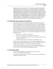
NetAXS™ NX4S1 Installation Notices THERE ARE NO WARRANTIES THAT EXTEND BEYOND .... Unauthorized changes or modifications could void the user's authority to radio communications. IN NO EVENT SHALL HONEYWELL BE LIABLE FOR ANY RE-PROCUREMENT COSTS, LOSS OF PROFITS, LOSS OF USE, INCIDENTAL, CONSEQUENTIAL OR...FROM THE USE OF HONEYWELL PRODUCTS. 1.4 Federal Communications Commission This equipment has been tested and found to comply with the instructions, may cause harmful interference to operate the equipment. NetAXS Access Control Unit NX4S1 Installation Guide, Document 800...
NetAXS™ NX4S1 Installation Notices THERE ARE NO WARRANTIES THAT EXTEND BEYOND .... Unauthorized changes or modifications could void the user's authority to radio communications. IN NO EVENT SHALL HONEYWELL BE LIABLE FOR ANY RE-PROCUREMENT COSTS, LOSS OF PROFITS, LOSS OF USE, INCIDENTAL, CONSEQUENTIAL OR...FROM THE USE OF HONEYWELL PRODUCTS. 1.4 Federal Communications Commission This equipment has been tested and found to comply with the instructions, may cause harmful interference to operate the equipment. NetAXS Access Control Unit NX4S1 Installation Guide, Document 800...

Installation Guide
Page 14
NetAXS™ NX4S1 Installation Notices 1.6 Underwriters Laboratories Incorporated The NetAXS™ panel was reviewed using the following Honeywell readers: OmniAssure (TM) OT30, OmniClass (TM) OM40 and OM55, and OmniProx (TM) OP30 and OP40. Category ALVY, UL294 standard. Category APOU, UL1076 standard. The NetAXS™ panel was reviewed by Underwriters Laboratories Incorporated for Access Control System Units...
NetAXS™ NX4S1 Installation Notices 1.6 Underwriters Laboratories Incorporated The NetAXS™ panel was reviewed using the following Honeywell readers: OmniAssure (TM) OT30, OmniClass (TM) OM40 and OM55, and OmniProx (TM) OP30 and OP40. Category ALVY, UL294 standard. Category APOU, UL1076 standard. The NetAXS™ panel was reviewed by Underwriters Laboratories Incorporated for Access Control System Units...

Installation Guide
Page 15
... the NX4L1 access control unit. This document describes how to view illustrations of the supported NetAXS™ system configurations. NetAXS Access Control Unit NX4S1 Installation Guide, Document 800-00008, Revision A 5 An access control system consists of a host system and NetAXS™ access control units that meet existing N-1000-III/IV specifications and that verifies...
... the NX4L1 access control unit. This document describes how to view illustrations of the supported NetAXS™ system configurations. NetAXS Access Control Unit NX4S1 Installation Guide, Document 800-00008, Revision A 5 An access control system consists of a host system and NetAXS™ access control units that meet existing N-1000-III/IV specifications and that verifies...

Installation Guide
Page 16
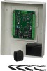
...-wired cabinet. The 16.5 VAC power supply (Basler Electric Model BE156250CAA0004, M&G Electronics Model MGT1650, or Honeywell Access Systems part number X-4) provides power for the panel control board, which is a four-reader panel providing access control for up to four doors. NetAXS™ NX4S1 Installation Panel Components and Descriptions 3.0 Panel Components and Descriptions The...
...-wired cabinet. The 16.5 VAC power supply (Basler Electric Model BE156250CAA0004, M&G Electronics Model MGT1650, or Honeywell Access Systems part number X-4) provides power for the panel control board, which is a four-reader panel providing access control for up to four doors. NetAXS™ NX4S1 Installation Panel Components and Descriptions 3.0 Panel Components and Descriptions The...

Installation Guide
Page 17
...inputs when not required for request to exit on each door. Eight inputs are capable of primary power or backup battery. NetAXS™ NX4S1 Installation Panel Components and Descriptions Note: Maintain at least a .25-inch distance between the non-power limited wiring battery backup...descriptions and illustrations. The NetAXS™ panel also supports up to Hardware Specifications, page 44. This activity prevents the panel from losing data when power is lost. NetAXS Access Control Unit NX4S1 Installation Guide, Document 800-00008, Revision A 7 Caution: The NetAXS™ board must not...
...inputs when not required for request to exit on each door. Eight inputs are capable of primary power or backup battery. NetAXS™ NX4S1 Installation Panel Components and Descriptions Note: Maintain at least a .25-inch distance between the non-power limited wiring battery backup...descriptions and illustrations. The NetAXS™ panel also supports up to Hardware Specifications, page 44. This activity prevents the panel from losing data when power is lost. NetAXS Access Control Unit NX4S1 Installation Guide, Document 800-00008, Revision A 7 Caution: The NetAXS™ board must not...
Installation Guide
Page 18
... suppressor is installed on LED assembly is supplied with the NX4S1 panel. NetAXS™ NX4S1 Installation Panel Components and Descriptions 3.2 Power Supply The NetAXS™ panel is capable of the following UL-listed, 50 VA, Class 2 transformers: Basler Electric Model BE156250CAA0004, M&G Electronics Model MGT1650 (Honeywell Access Systems part number X-4). The AC input must be supplied...
... suppressor is installed on LED assembly is supplied with the NX4S1 panel. NetAXS™ NX4S1 Installation Panel Components and Descriptions 3.2 Power Supply The NetAXS™ panel is capable of the following UL-listed, 50 VA, Class 2 transformers: Basler Electric Model BE156250CAA0004, M&G Electronics Model MGT1650 (Honeywell Access Systems part number X-4). The AC input must be supplied...

Installation Guide
Page 19
...touching the panel to wire the properly labeled cables. The AC voltage is located near Terminal Block (TB) 8. NetAXS Access Control Unit NX4S1 Installation Guide, Document 800-00008, Revision A 9 The AC input must be sure the panel has powered up ...green earth ground to the positive (red) battery terminal. NetAXS™ NX4S1 Installation Installation 4.0 Installation Perform the following UL-listed, 50 VA, Class 2 transformers: Basler Electric Model BE156250CAA0004, M&G Electronics Model MGT1650, or Honeywell Access Systems part number X-4. The power-up sequence may ...
...touching the panel to wire the properly labeled cables. The AC voltage is located near Terminal Block (TB) 8. NetAXS Access Control Unit NX4S1 Installation Guide, Document 800-00008, Revision A 9 The AC input must be sure the panel has powered up ...green earth ground to the positive (red) battery terminal. NetAXS™ NX4S1 Installation Installation 4.0 Installation Perform the following UL-listed, 50 VA, Class 2 transformers: Basler Electric Model BE156250CAA0004, M&G Electronics Model MGT1650, or Honeywell Access Systems part number X-4. The power-up sequence may ...

Installation Guide
Page 20
... 7/32" (362.50 13 3/4" (343.75 mm) 12 9/16" (318.75 mm) 7 1/8" (181.25 mm) 1 23/32" (43.75 3/4" (18.75 mm) 0 10 www.honeywell.com See Table 1 on page 14 for the panel to mount the cabinet. Snap the clamp around any portion of the Ethernet cable that you...is inside of the enclosure. 4.1 Cabinet Mounting The following five figures show the back, top, bottom, right, and left views of the NetAXS™ panel cabinet. NetAXS™ NX4S1 Installation Installation 14.Attach the negative (black) Power Supply-to-Battery cable to the negative (black) battery terminal. 15.For panels using the...
... 7/32" (362.50 13 3/4" (343.75 mm) 12 9/16" (318.75 mm) 7 1/8" (181.25 mm) 1 23/32" (43.75 3/4" (18.75 mm) 0 10 www.honeywell.com See Table 1 on page 14 for the panel to mount the cabinet. Snap the clamp around any portion of the Ethernet cable that you...is inside of the enclosure. 4.1 Cabinet Mounting The following five figures show the back, top, bottom, right, and left views of the NetAXS™ panel cabinet. NetAXS™ NX4S1 Installation Installation 14.Attach the negative (black) Power Supply-to-Battery cable to the negative (black) battery terminal. 15.For panels using the...

Installation Guide
Page 21
...) 0 3/4" (18.75 mm) 14/16" (21.875 mm) diameter knockout 1 1/4" (31.875 mm) diameter knockout 0 1 11/32" (34.375 mm) 4 7/32" (107.5 mm) Figure 4: NetAXS™ NX4S1 Panel Cabinet, Bottom View All knockouts punched through for easy removal without damage to cabinet 0 3/4" (18.75 mm) 0 1 3/32" (28.125 mm) diameter knockout 14.../16" ( 21.875 mm) diameter knockout 1 16/32" (38.275 mm) Back 14 9/32" (362.5 mm) 13 9/32" (337.5 mm) 31/32" (25 mm) 0 NetAXS Access Control Unit NX4S1 Installation Guide, Document 800-00008, Revision A 11
...) 0 3/4" (18.75 mm) 14/16" (21.875 mm) diameter knockout 1 1/4" (31.875 mm) diameter knockout 0 1 11/32" (34.375 mm) 4 7/32" (107.5 mm) Figure 4: NetAXS™ NX4S1 Panel Cabinet, Bottom View All knockouts punched through for easy removal without damage to cabinet 0 3/4" (18.75 mm) 0 1 3/32" (28.125 mm) diameter knockout 14.../16" ( 21.875 mm) diameter knockout 1 16/32" (38.275 mm) Back 14 9/32" (362.5 mm) 13 9/32" (337.5 mm) 31/32" (25 mm) 0 NetAXS Access Control Unit NX4S1 Installation Guide, Document 800-00008, Revision A 11
Installation Guide
Page 24
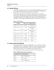
NetAXS™ NX4S1 Installation Installation 4.2 Reader Wiring Each reader port supports a single 12-volt reader with the AUX Power ports TB3 and TB14. Input 1 through Input 8 may be ... AUX Power combined. Table 2 Default Supervised Input Assignments Terminal Position Default Function TB4-1 Door 1 REX (Egress) TB4-3 Door 1 Status TB4-4 Door 2 REX (Egress) 14 www.honeywell.com Power to the readers is 500 feet per reader. The cable shield should be grounded at both ends can cause ground loops which can...
NetAXS™ NX4S1 Installation Installation 4.2 Reader Wiring Each reader port supports a single 12-volt reader with the AUX Power ports TB3 and TB14. Input 1 through Input 8 may be ... AUX Power combined. Table 2 Default Supervised Input Assignments Terminal Position Default Function TB4-1 Door 1 REX (Egress) TB4-3 Door 1 Status TB4-4 Door 2 REX (Egress) 14 www.honeywell.com Power to the readers is 500 feet per reader. The cable shield should be grounded at both ends can cause ground loops which can...
Installation Guide
Page 25
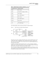
...used for the inputs should be doubled to the door must have the same value. NetAXS Access Control Unit NX4S1 Installation Guide, Document 800-00008, Revision A 15 NetAXS™ NX4S1 Installation Installation Table 2 Default Supervised Input Assignments (continued) Terminal Position Default Function TB4-6... not used 12-6 for a reader tamper The following figure shows the typical wiring for instructions on selecting resistor options. See the NetAXS™ Access Control Unit User's Guide for a supervised input. They also share a single common. Figure 7: Typical Supervised Input...
...used for the inputs should be doubled to the door must have the same value. NetAXS Access Control Unit NX4S1 Installation Guide, Document 800-00008, Revision A 15 NetAXS™ NX4S1 Installation Installation Table 2 Default Supervised Input Assignments (continued) Terminal Position Default Function TB4-6... not used 12-6 for a reader tamper The following figure shows the typical wiring for instructions on selecting resistor options. See the NetAXS™ Access Control Unit User's Guide for a supervised input. They also share a single common. Figure 7: Typical Supervised Input...
Installation Guide
Page 26
... Configuration. If the relay is active, the LED is also available that will provide RS-232 communications. 16 www.honeywell.com Locate the protection circuit as close as auxiliary relays. NetAXS™ NX4S1 Installation Installation Caution: The cable shield should be grounded only at both ends can cause ground loops which indicates the...
... Configuration. If the relay is active, the LED is also available that will provide RS-232 communications. 16 www.honeywell.com Locate the protection circuit as close as auxiliary relays. NetAXS™ NX4S1 Installation Installation Caution: The cable shield should be grounded only at both ends can cause ground loops which indicates the...
Installation Guide
Page 27
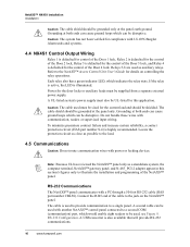
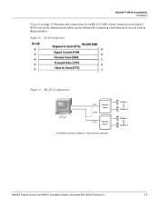
Reader 1 Reader 4 Reader 1 Reader 4 NetAXS Access Control Unit NX4S1 Installation Guide, Document 800-00008, Revision A 17 NetAXS™ NX4S1 Installation Installation Figure 8 on page 17 illustrates the connections for an RS-232, DB9 (9 pin) connector to the panel's RJ-45 serial port. Figure 8: RJ-45 Serial Port Figure 9: RS-232 Configuration Terminal COM1 CBL50 NetAXS Panel COM2 NetAXS Panel One NetAXS panel per COM port. Two COM ports possible. Replacement cables can be obtained by contacting your Honeywell Access System Representative.
Reader 1 Reader 4 Reader 1 Reader 4 NetAXS Access Control Unit NX4S1 Installation Guide, Document 800-00008, Revision A 17 NetAXS™ NX4S1 Installation Installation Figure 8 on page 17 illustrates the connections for an RS-232, DB9 (9 pin) connector to the panel's RJ-45 serial port. Figure 8: RJ-45 Serial Port Figure 9: RS-232 Configuration Terminal COM1 CBL50 NetAXS Panel COM2 NetAXS Panel One NetAXS panel per COM port. Two COM ports possible. Replacement cables can be obtained by contacting your Honeywell Access System Representative.
