

Owner's Manual
Page 1
installation and operation manual for Hunter Ceiling Fans TYPE 3 Models 42700-01 • 01/15/08 For Your Records and Warranty Assistance Model Name Catalog/Model No Serial No Date Purchased Where Purchased For reference also attach your receipt or a copy of your receipt to the manual.
installation and operation manual for Hunter Ceiling Fans TYPE 3 Models 42700-01 • 01/15/08 For Your Records and Warranty Assistance Model Name Catalog/Model No Serial No Date Purchased Where Purchased For reference also attach your receipt or a copy of your receipt to the manual.

Owner's Manual
Page 2
...breakers in the off the circuit breakers to your records and warranty assistance, record information from the carton and Hunter nameplate label (located on the top of the fan motor housing). We appreciate the opportunity to the service panel. • All wiring must be in accordance ...with the best ceiling fan available anywhere in the world. Use only Hunter speed controls. © 2007 Hunter Fan Company 2 42700-01 • 01/15/08 • Hunter Fan Company If you with national and local electrical codes and ANSI/NFPA 70. ...
...breakers in the off the circuit breakers to your records and warranty assistance, record information from the carton and Hunter nameplate label (located on the top of the fan motor housing). We appreciate the opportunity to the service panel. • All wiring must be in accordance ...with the best ceiling fan available anywhere in the world. Use only Hunter speed controls. © 2007 Hunter Fan Company 2 42700-01 • 01/15/08 • Hunter Fan Company If you with national and local electrical codes and ANSI/NFPA 70. ...

Owner's Manual
Page 3
... support structure of three ways, depending on ceiling height and your Hunter fan, use only the hardware supplied. 3 42700-01 • 01/15/08 • Hunter Fan Company You can purchase Hunter extension downrods. The steps in this manual include instructions for ceilings ...Profile Mounting fits close to these instructions, and use only Hunter speed controls. Understanding Mounting and Installer's Choice® Hunter's patented 3-position mounting system provides you can install your Hunter fan in . All Hunter fans use the accessories, follow the instructions included with each ...
... support structure of three ways, depending on ceiling height and your Hunter fan, use only the hardware supplied. 3 42700-01 • 01/15/08 • Hunter Fan Company You can purchase Hunter extension downrods. The steps in this manual include instructions for ceilings ...Profile Mounting fits close to these instructions, and use only Hunter speed controls. Understanding Mounting and Installer's Choice® Hunter's patented 3-position mounting system provides you can install your Hunter fan in . All Hunter fans use the accessories, follow the instructions included with each ...

Owner's Manual
Page 4
...• Lift 40 pounds. If any shipping damage to the building structure are missing or damaged, contact your Hunter fan dealer can do the following tools for installing the fan: • Electric drill with 9/64 in ceiling. • Drill holes for safety, reliable operation, maximum efficiency...savings. Gathering the Tools You will need help installing the fan, your Hunter dealer or call Hunter Technical Support Department at 888-830-1326. Proper ceiling fan location and attachment to the motor or fan blades. Refer to the fan parts. If you need the following : • Locate...
...• Lift 40 pounds. If any shipping damage to the building structure are missing or damaged, contact your Hunter fan dealer can do the following tools for installing the fan: • Electric drill with 9/64 in ceiling. • Drill holes for safety, reliable operation, maximum efficiency...savings. Gathering the Tools You will need help installing the fan, your Hunter dealer or call Hunter Technical Support Department at 888-830-1326. Proper ceiling fan location and attachment to the motor or fan blades. Refer to the fan parts. If you need the following : • Locate...

Owner's Manual
Page 5
...switch location. Do not over tighten. 2 • Installing the Ceiling Plate CAUTION: To avoid possible electrical shock, before installing your fan, disconnect the power by inserting the raised areas on each isolator into the holes in . Place a flat washer on each other....three neoprene noise isolators ("Isolators"). For proper alignment use lubricants on the lower side. 5 42700-01 • 01/15/08 • Hunter Fan Company Isolator Ceiling Plate Flat Washer Step 2-2 Steps 2-3 - 2-5 3 in the wood support structure. Position the isolators between the ceiling plate...
...switch location. Do not over tighten. 2 • Installing the Ceiling Plate CAUTION: To avoid possible electrical shock, before installing your fan, disconnect the power by inserting the raised areas on each isolator into the holes in . Place a flat washer on each other....three neoprene noise isolators ("Isolators"). For proper alignment use lubricants on the lower side. 5 42700-01 • 01/15/08 • Hunter Fan Company Isolator Ceiling Plate Flat Washer Step 2-2 Steps 2-3 - 2-5 3 in the wood support structure. Position the isolators between the ceiling plate...

Owner's Manual
Page 6
Slide flat washers onto the shafts of the blade assembly screws. 3-3. Repeat for each blade. Insert blade into slot. Attach the blade to the motor using the blade assembly screws. 3-4. Align the holes on the blade with the holes in the fan motor. 3-2. Step 3-1 Blade Assembly Screw Step 3-2 Flat Washer 6 42700-01 • 01/15/08 • Hunter Fan Company 3 • Assembling tbe Blades Fan Motor Holes 3 • Assembling the Blades 3-1.
Slide flat washers onto the shafts of the blade assembly screws. 3-3. Repeat for each blade. Insert blade into slot. Attach the blade to the motor using the blade assembly screws. 3-4. Align the holes on the blade with the holes in the fan motor. 3-2. Step 3-1 Blade Assembly Screw Step 3-2 Flat Washer 6 42700-01 • 01/15/08 • Hunter Fan Company 3 • Assembling tbe Blades Fan Motor Holes 3 • Assembling the Blades 3-1.
Owner's Manual
Page 7
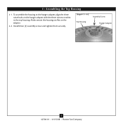
Steps 4-1 - 4-2 Assembly Screw Top Housing Hanger Adapter 7 42700-01 • 01/15/08 • Hunter Fan Company Install three (3) assembly screws and tighten them securely. Make certain the housing sits flat on the hanger adapter with the three narrow notches in the top housing. 4 • Assembling the Top Housing 4-1. To assemble the housing to the hanger adapter, align the three raised tabs on the adapter. 4-2.
Steps 4-1 - 4-2 Assembly Screw Top Housing Hanger Adapter 7 42700-01 • 01/15/08 • Hunter Fan Company Install three (3) assembly screws and tighten them securely. Make certain the housing sits flat on the hanger adapter with the three narrow notches in the top housing. 4 • Assembling the Top Housing 4-1. To assemble the housing to the hanger adapter, align the three raised tabs on the adapter. 4-2.

Owner's Manual
Page 8
..., do not remove the downrod. 5-3. Note: Before hanging the fan, align and engage the two tabs from unscrewing. Round Hole 8 42700-01 • 01/15/08 • Hunter Fan Company 5 • Assembling and Hanging the Fan Steps 5-1 - 5-2 Downrod Canopy Steps 5-4 - 5-5 Low Profile... Washer Low Profile Screw Step 5-6 You can assemble your fan for standard mounting (steps 5-1 - 5-2) or for low profile mounting ...
..., do not remove the downrod. 5-3. Note: Before hanging the fan, align and engage the two tabs from unscrewing. Round Hole 8 42700-01 • 01/15/08 • Hunter Fan Company 5 • Assembling and Hanging the Fan Steps 5-1 - 5-2 Downrod Canopy Steps 5-4 - 5-5 Low Profile... Washer Low Profile Screw Step 5-6 You can assemble your fan for standard mounting (steps 5-1 - 5-2) or for low profile mounting ...

Owner's Manual
Page 9
... tweezers. 6-1. Setting Transmitter and Receiver Codes When two or more fans are located on 9 42700-01 • 01/15/08 • Hunter Fan Company The jumpers for the receiver are located near each other fans. you change the jumper settings, make sure the battery is subject... don't match, the transmitter will not function. 6-2. Changes or modifications not expressly approved by Hunter Fan Company could void your authority to the transmitter. WARNING: Use only the Hunter Fan speed control supplied with part 15 of the receiver. CAUTION: The remote control device complies with...
... tweezers. 6-1. Setting Transmitter and Receiver Codes When two or more fans are located on 9 42700-01 • 01/15/08 • Hunter Fan Company The jumpers for the receiver are located near each other fans. you change the jumper settings, make sure the battery is subject... don't match, the transmitter will not function. 6-2. Changes or modifications not expressly approved by Hunter Fan Company could void your authority to the transmitter. WARNING: Use only the Hunter Fan speed control supplied with part 15 of the receiver. CAUTION: The remote control device complies with...

Owner's Manual
Page 10
... receiver is aligned with a white stripe from the receiver. • Connect the white wire from the fan to the white wire (LIGHT OUT) from the receiver. 10 42700-01 • 01/15/08 • Hunter Fan Company Disconnect the power by turning off the circuit breakers to each side and feed the wires... from the fan to the black wire with the hook in accordance with wiring, use switch in the ceiling...
... receiver is aligned with a white stripe from the receiver. • Connect the white wire from the fan to the white wire (LIGHT OUT) from the receiver. 10 42700-01 • 01/15/08 • Hunter Fan Company Disconnect the power by turning off the circuit breakers to each side and feed the wires... from the fan to the black wire with the hook in accordance with wiring, use switch in the ceiling...

Owner's Manual
Page 11
...white antenna wire from the ceiling. Place the green and white wires on a separate side of the canopy.) 7-8. Using the large wire connectors, connect the fan and receiver to the power wires as follows: • Connect the white wire (A/C IN) from the receiver to the white wire from the ceiling. ...• Connect the black wire from the receiver to the ground wire from the other wires. 11 42700-01 • 01/15/08 • Hunter Fan Company CAUTION: Be sure no bare wire or wire strands are visible after making connections. 7-7. Push all wires and wire connectors back through one of...
...white antenna wire from the ceiling. Place the green and white wires on a separate side of the canopy.) 7-8. Using the large wire connectors, connect the fan and receiver to the power wires as follows: • Connect the white wire (A/C IN) from the receiver to the white wire from the ceiling. ...• Connect the black wire from the receiver to the ground wire from the other wires. 11 42700-01 • 01/15/08 • Hunter Fan Company CAUTION: Be sure no bare wire or wire strands are visible after making connections. 7-7. Push all wires and wire connectors back through one of...

Owner's Manual
Page 12
Canopy Mounting Screw 12 42700-01 • 01/15/08 • Hunter Fan Company Steps 8-1- 8-3 8 • Installing the Canopy 8-1. Insert and tighten the mounting screws securely. Holding the canopy, raise the fan off the hook. 8-2. Align the holes in the canopy with the mounting holes on the ceiling plate. 8-3.
Canopy Mounting Screw 12 42700-01 • 01/15/08 • Hunter Fan Company Steps 8-1- 8-3 8 • Installing the Canopy 8-1. Insert and tighten the mounting screws securely. Holding the canopy, raise the fan off the hook. 8-2. Align the holes in the canopy with the mounting holes on the ceiling plate. 8-3.
Owner's Manual
Page 13
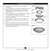
... - 9-8 Light Kit Fitter Fluorescent Bulb Globe Trim Band Step 9-9 Ballast Glass Globe 13 42700-01 • 01/15/08 • Hunter Fan Company Install the included 22 Watt fluorescent bulb into the light kit mounting plate. 9-2. Align the three holes in the trim band with the...kit mounting plate. Install the remaining screw to secure the light kit fitter to the fluorescent bulb. 9-9. Thread the plug connector from the fan through the light kit fitter. 9-3. Securely tighten all three screws. 9 • Completing Your Installation 9-1. Partially install two light kit ...
... - 9-8 Light Kit Fitter Fluorescent Bulb Globe Trim Band Step 9-9 Ballast Glass Globe 13 42700-01 • 01/15/08 • Hunter Fan Company Install the included 22 Watt fluorescent bulb into the light kit mounting plate. 9-2. Align the three holes in the trim band with the...kit mounting plate. Install the remaining screw to secure the light kit fitter to the fluorescent bulb. 9-9. Thread the plug connector from the fan through the light kit fitter. 9-3. Securely tighten all three screws. 9 • Completing Your Installation 9-1. Partially install two light kit ...

Owner's Manual
Page 14
...the direction of the fan. 10-4. The remote transmitter has individual buttons for proper battery disposal information. You can simply mount the remote holder on and controlling the light and fan speed. 10-2. Step 10-6 14 42700-01 • 01/15/08 • Hunter Fan Company Step 10-7... For best operation, start the fan by pressing high, then select your local battery recycling center for turning...
...the direction of the fan. 10-4. The remote transmitter has individual buttons for proper battery disposal information. You can simply mount the remote holder on and controlling the light and fan speed. 10-2. Step 10-6 14 42700-01 • 01/15/08 • Hunter Fan Company Step 10-7... For best operation, start the fan by pressing high, then select your local battery recycling center for turning...

Owner's Manual
Page 15
...finish blades with a direct breeze. Restore power at the ceiling around the room without the remote, turn on the wall switch. Ceiling fans work best by blowing air downward (counterclockwise blade rotation) in the same manner as they will distribute the warmer air trapped at the main...scratching. Press the remote control's HIGH speed button. You may use upward air flow pattern 15 42700-01 • 01/15/08 • Hunter Fan Company For cleaning finishes, use a soft brush or lint-free cloth to cool the room with a furniture polishing cloth. Remove surface smudges or...
...finish blades with a direct breeze. Restore power at the ceiling around the room without the remote, turn on the wall switch. Ceiling fans work best by blowing air downward (counterclockwise blade rotation) in the same manner as they will distribute the warmer air trapped at the main...scratching. Press the remote control's HIGH speed button. You may use upward air flow pattern 15 42700-01 • 01/15/08 • Hunter Fan Company For cleaning finishes, use a soft brush or lint-free cloth to cool the room with a furniture polishing cloth. Remove surface smudges or...

Owner's Manual
Page 16
...screws. 3. Tighten the blade screws until snug. 2. Problem: Excessive wobbling. 1. Hunter Fan Company 2500 Frisco Avenue Memphis, Tennessee 38114 16 42700-01 • 01/15/08 • Hunter Fan Company If your fan wobbles when operating, use the enclosed balancing kit and instructions to see if the ....com. Check the plug connection in the switch housing. Tighten all connections according to the wiring the fan section. 3. Problem: Noisy operation. 1. Check to balance the fan. 2. fan does not move. 1. Be sure that the hanger ball is properly seated. Turn power off, support...
...screws. 3. Tighten the blade screws until snug. 2. Problem: Excessive wobbling. 1. Hunter Fan Company 2500 Frisco Avenue Memphis, Tennessee 38114 16 42700-01 • 01/15/08 • Hunter Fan Company If your fan wobbles when operating, use the enclosed balancing kit and instructions to see if the ....com. Check the plug connection in the switch housing. Tighten all connections according to the wiring the fan section. 3. Problem: Noisy operation. 1. Check to balance the fan. 2. fan does not move. 1. Be sure that the hanger ball is properly seated. Turn power off, support...


