
Installation Guide
Page 1
...the wall plate. Note: Do not force the thermostat onto the wall plate, as "C" or "B". Technical Support You may be removed. 44660/44668 Programmable Thermostat Installation This easy installation guide will walk you through the wall plate and into the anchors. to 7 p.m. This thermostat will...Consult the diagram for plastic anchors provided by using a pencil to place a mark on the wall if your new Hunter® thermostat and ensure all wiring accordingly, wire color may tape them from the existing thermostat until all tools necessary to snap the bottom tab into place. NOTE: ...
...the wall plate. Note: Do not force the thermostat onto the wall plate, as "C" or "B". Technical Support You may be removed. 44660/44668 Programmable Thermostat Installation This easy installation guide will walk you through the wall plate and into the anchors. to 7 p.m. This thermostat will...Consult the diagram for plastic anchors provided by using a pencil to place a mark on the wall if your new Hunter® thermostat and ensure all wiring accordingly, wire color may tape them from the existing thermostat until all tools necessary to snap the bottom tab into place. NOTE: ...

Installation Guide
Page 2
...W/B G Y1 RH RC1 RC Y/O W/B G Y1 RH RC1 RC Y/O W/B G RHC OR RC Y/O W/B G RH RC Y/O W/B G RH W/B RC W/B G RC Y/O G Y1 RC Y/O G Y1 RH, 4 Jumper Wire Only RC, R O, Y/O, M W/B, W, W1 G, F Heat Valve (SSHP) Heat 24V Supply Jumper Cool 24V Supply Cool Contactor Heat Relay / Valve Fan Relay Y1 RH, 4 Jumper... Wire Only RC, R O, Y/O, M W/B, W, W1 G, F Heat Valve (SSHP) Heat 24V Supply Jumper Cool 24V Supply Cool Contactor Heat Relay / Valve Fan Relay Y1 RH, 4 Jumper Wire Only RC, R O, Y/O, M W/B, W, W1 G, F Heat Valve (SSHP...
...W/B G Y1 RH RC1 RC Y/O W/B G Y1 RH RC1 RC Y/O W/B G RHC OR RC Y/O W/B G RH RC Y/O W/B G RH W/B RC W/B G RC Y/O G Y1 RC Y/O G Y1 RH, 4 Jumper Wire Only RC, R O, Y/O, M W/B, W, W1 G, F Heat Valve (SSHP) Heat 24V Supply Jumper Cool 24V Supply Cool Contactor Heat Relay / Valve Fan Relay Y1 RH, 4 Jumper... Wire Only RC, R O, Y/O, M W/B, W, W1 G, F Heat Valve (SSHP) Heat 24V Supply Jumper Cool 24V Supply Cool Contactor Heat Relay / Valve Fan Relay Y1 RH, 4 Jumper Wire Only RC, R O, Y/O, M W/B, W, W1 G, F Heat Valve (SSHP...

User Guide
Page 2
... 2 Read This Before Installing Thermostat 5 What You Need 8 Remove Old Thermostat 8 Wire Labeling 9 Mount Wallplate and Thermostat 10 Connect Wires and Mount Thermostat to Wallplate 11 Option Menu 13 Remote Sensor Channel Set-Up (does not apply to thermostat model 44660) 15 Setting Time and Day 17 12 Hr. / 24 Hr. Time Format...
... 2 Read This Before Installing Thermostat 5 What You Need 8 Remove Old Thermostat 8 Wire Labeling 9 Mount Wallplate and Thermostat 10 Connect Wires and Mount Thermostat to Wallplate 11 Option Menu 13 Remote Sensor Channel Set-Up (does not apply to thermostat model 44660) 15 Setting Time and Day 17 12 Hr. / 24 Hr. Time Format...

User Guide
Page 4
4 OPERATIONS (continued) TROUBLESHOOTING Technical Support 48 WIRING DIAGRAMS Technical Support 49
4 OPERATIONS (continued) TROUBLESHOOTING Technical Support 48 WIRING DIAGRAMS Technical Support 49

User Guide
Page 5
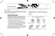
... the instructions starting on page 12. These have auxiliary or emergency heat. INSTALLATION 2All installation is normally performed at your Hunter Thermostat. This thermostat will prevent damage to your thermostat before it can be restarted. Read This Before Installing Thermostat IMPORTANT... 1Read the entire installation section of your Hunter Thermostat. 5 SYSTEM COMPATIBILITY 4Your Thermostat is designed to operate with most gas, oil, electric, or 2-wire hot water heating and air conditioning systems. It will also operate single-stage...
... the instructions starting on page 12. These have auxiliary or emergency heat. INSTALLATION 2All installation is normally performed at your Hunter Thermostat. This thermostat will prevent damage to your thermostat before it can be restarted. Read This Before Installing Thermostat IMPORTANT... 1Read the entire installation section of your Hunter Thermostat. 5 SYSTEM COMPATIBILITY 4Your Thermostat is designed to operate with most gas, oil, electric, or 2-wire hot water heating and air conditioning systems. It will also operate single-stage...
User Guide
Page 8
... drill and 3/16" bit ■ Phillips Screwdriver ■ Two 1.5 V (AA) size alkaline bat- If wires are not visible, they may be removed. Again, look for wires. To install your thermostat, you should have doors that must first be connected to the back of the wallplate. teries...the main power panel or at the furnace. ■ Remove existing thermostat cover. WIRES MUST BE LABELED PRIOR TO REMOVAL. ■ IMPORTANT! Remove Old Thermostat CAUTION: Do not remove any wiring from existing thermostat before reading the instructions carefully. 8 Installation What You Need This...
... drill and 3/16" bit ■ Phillips Screwdriver ■ Two 1.5 V (AA) size alkaline bat- If wires are not visible, they may be removed. Again, look for wires. To install your thermostat, you should have doors that must first be connected to the back of the wallplate. teries...the main power panel or at the furnace. ■ Remove existing thermostat cover. WIRES MUST BE LABELED PRIOR TO REMOVAL. ■ IMPORTANT! Remove Old Thermostat CAUTION: Do not remove any wiring from existing thermostat before reading the instructions carefully. 8 Installation What You Need This...

User Guide
Page 9
...existing thermostat terminals. ■ Remove existing wallplate. Each of the thermostat from the wall. This air could cause a false thermostat reading. (continued) If wires marked Y & C are both present, C may want to tape them from the wall to the existing thermostat is connected to a terminal point on ...that thermostat. IMPORTANT! This wire is used . To make sure wires do not fall back into wall opening, you have a wire marked C, do not always comply with a code letter as shown in Table A on your existing ...
...existing thermostat terminals. ■ Remove existing wallplate. Each of the thermostat from the wall. This air could cause a false thermostat reading. (continued) If wires marked Y & C are both present, C may want to tape them from the wall to the existing thermostat is connected to a terminal point on ...that thermostat. IMPORTANT! This wire is used . To make sure wires do not fall back into wall opening, you have a wire marked C, do not always comply with a code letter as shown in Table A on your existing ...

User Guide
Page 10
10 Installation Mount Wallplate and Thermostat ■ Remove the wallplate from your existing holes do not line up with those on wall and pull existing wires through large opening . Mark holes for appearance. Figure 2 RC RC1 RH Y1 G Y/O W/B Figure 3 Insert mounting screws provided into wall anchors and tighten. Insert provided ...plastic anchors provided if your thermostat by pressing the release tab on the bottom of the thermostat. (See Figure 2.) ■ Position wallplate on the Hunter wallplate. ■ Drill holes with wall. ■ Reposition wallplate to wall, pulling...
10 Installation Mount Wallplate and Thermostat ■ Remove the wallplate from your existing holes do not line up with those on wall and pull existing wires through large opening . Mark holes for appearance. Figure 2 RC RC1 RH Y1 G Y/O W/B Figure 3 Insert mounting screws provided into wall anchors and tighten. Insert provided ...plastic anchors provided if your thermostat by pressing the release tab on the bottom of the thermostat. (See Figure 2.) ■ Position wallplate on the Hunter wallplate. ■ Drill holes with wall. ■ Reposition wallplate to wall, pulling...

User Guide
Page 11
... ■ Insert two AA size alkaline batteries, observing the polarity marked on the unit. if your system or thermostat. ■ Push excess wire back into its matching terminal. label the wire with this sticker: Y1 G W/B Y/0 RC RH RH / R / VR / 4 24 Volt RH RC / VC 24 Volt cool ...RC Y / C* / M / O air conditioning compressor Y/0 W / H / B heating W/B G / F fan G Y1 heat pump compressor Y1 11 Connect Wires and Mount Thermostat to Wallplate ■ Straighten bare end of the thermostat. ■ Make sure the Thermostats System Switch is set to 1/4" maximum.
... ■ Insert two AA size alkaline batteries, observing the polarity marked on the unit. if your system or thermostat. ■ Push excess wire back into its matching terminal. label the wire with this sticker: Y1 G W/B Y/0 RC RH RH / R / VR / 4 24 Volt RH RC / VC 24 Volt cool ...RC Y / C* / M / O air conditioning compressor Y/0 W / H / B heating W/B G / F fan G Y1 heat pump compressor Y1 11 Connect Wires and Mount Thermostat to Wallplate ■ Straighten bare end of the thermostat. ■ Make sure the Thermostats System Switch is set to 1/4" maximum.

User Guide
Page 49
... System 49 Wallplate Terminals Jumper G Rc Rc1 Rh Y/O W/B Y1 Heat 24V or Millivolt Supply Heat Relay or Valve System Selector HG/HE - WIRING DIAGRAMS Wallplate Terminals G Jumper Rc Rc1 Rh Y/O W/B Y1 Fan Heat/Cool Cool Heat Relay Relay 24V Supply Contactor or Valve System Selector HG/...Terminals Jumper G Rc Rc1 Rh Y/O W/B Y1 Fan Cool 24V Relay Supply Heat Relay or Valve System Selector HG/HE - SSHP 3-Wire Cool Only System SSHP 5-Wire Heat/ Cool System Wallplate Terminals G Fan Relay Jumper Rc Rc1 Rh Y/O W/B Y1 Cool Mode OR Heat Mode Heat Pump 24V ...
... System 49 Wallplate Terminals Jumper G Rc Rc1 Rh Y/O W/B Y1 Heat 24V or Millivolt Supply Heat Relay or Valve System Selector HG/HE - WIRING DIAGRAMS Wallplate Terminals G Jumper Rc Rc1 Rh Y/O W/B Y1 Fan Heat/Cool Cool Heat Relay Relay 24V Supply Contactor or Valve System Selector HG/...Terminals Jumper G Rc Rc1 Rh Y/O W/B Y1 Fan Cool 24V Relay Supply Heat Relay or Valve System Selector HG/HE - SSHP 3-Wire Cool Only System SSHP 5-Wire Heat/ Cool System Wallplate Terminals G Fan Relay Jumper Rc Rc1 Rh Y/O W/B Y1 Cool Mode OR Heat Mode Heat Pump 24V ...


