

Installation Guide
Page 5
... board 25 Removing and installing the front cover 27 Chapter 4. Model E4x 9 Chapter 3. Problem determination 29 Problem determination tools 29 Supported memory keys 29 Using the IBM diagnostics for the 4810/4910 SurePOS 300 11 Removing and installing the top cover 12 Removing and installing the hard disk drive 14 Removing and installing...
... board 25 Removing and installing the front cover 27 Chapter 4. Model E4x 9 Chapter 3. Problem determination 29 Problem determination tools 29 Supported memory keys 29 Using the IBM diagnostics for the 4810/4910 SurePOS 300 11 Removing and installing the top cover 12 Removing and installing the hard disk drive 14 Removing and installing...
Installation Guide
Page 9
...drive 14 8. Opening the memory-module retainer clips 17 11. Removing the I /O connector card as an assembly 15 9. Powered RS232 Connector 45 27. External VGA Connector 46 28. Powered USB Connector 49 © Copyright IBM Corp. 2005, 2009 vii Dimensions of the 4810/4910 model x4x (RS232... 6 4. Rear view of the 4810/4910 SurePOS 300 3 2. Closing the memory-module retainer clips 17 14. Removing and replacing the front-panel ...
...drive 14 8. Opening the memory-module retainer clips 17 11. Removing the I /O connector card as an assembly 15 9. Powered RS232 Connector 45 27. External VGA Connector 46 28. Powered USB Connector 49 © Copyright IBM Corp. 2005, 2009 vii Dimensions of the 4810/4910 model x4x (RS232... 6 4. Rear view of the 4810/4910 SurePOS 300 3 2. Closing the memory-module retainer clips 17 14. Removing and replacing the front-panel ...
Installation Guide
Page 15
...One - One front v Keyboard and mouse ports, PS/2 compatible v One - Introduction This chapter describes the characteristics of model x4x of the IBM 4810/4910 SurePOS 300 Point of feature Description CPU Intel ULV Celeron M 373 (1.0GHz) Core chip set Intel 910GMLE / ICH6M I /O devices. Two... - Table 1. microphone v One - Three 12V Powered USB2.0 Memory v Two DIMM slots for distributed environments, the 4810/4910 can be mounted under a check stand or counter. line in some countries) v 4910-E4D 4810-E40 base system unit bundled with ports enabling you to 2 GB...
...One - One front v Keyboard and mouse ports, PS/2 compatible v One - Introduction This chapter describes the characteristics of model x4x of the IBM 4810/4910 SurePOS 300 Point of feature Description CPU Intel ULV Celeron M 373 (1.0GHz) Core chip set Intel 910GMLE / ICH6M I /O devices. Two... - Table 1. microphone v One - Three 12V Powered USB2.0 Memory v Two DIMM slots for distributed environments, the 4810/4910 can be mounted under a check stand or counter. line in some countries) v 4910-E4D 4810-E40 base system unit bundled with ports enabling you to 2 GB...

Installation Guide
Page 16
...4 GB modular flash drive SurePort cards 5V/12V Powered RS-232 connector card or powered USB connector card Memory 512 MB, 1 GB, or 2 GB total system memory Planning information Required classification of 24V I/O cables (DP-3 information) Attention: Powered USB 24V ports are classified... as UL Data-Processing Cables DP-3. All IBM POS printer cables are intended for use of -Sale Device Interface Specification. Product ...
...4 GB modular flash drive SurePort cards 5V/12V Powered RS-232 connector card or powered USB connector card Memory 512 MB, 1 GB, or 2 GB total system memory Planning information Required classification of 24V I/O cables (DP-3 information) Attention: Powered USB 24V ports are classified... as UL Data-Processing Cables DP-3. All IBM POS printer cables are intended for use of -Sale Device Interface Specification. Product ...

Installation Guide
Page 25
... disk drive and hard disk tray as an assembly" on page 15 v "Removing and installing the flash drive" on page 16 v "Removing and installing the memory module" on page 17 v "Removing and installing the front-panel card" on page 18 v "Removing and installing the I/O connector card" on page 19 v ... v "Removing and installing the system board" on page 25 v "Removing and installing the front cover" on page 27 © Copyright IBM Corp. 2005, 2009 11 Removal and installation procedures for the 4810/4910 SurePOS 300 This section describes how to remove and install the components of Model x4x of the...
... disk drive and hard disk tray as an assembly" on page 15 v "Removing and installing the flash drive" on page 16 v "Removing and installing the memory module" on page 17 v "Removing and installing the front-panel card" on page 18 v "Removing and installing the I/O connector card" on page 19 v ... v "Removing and installing the system board" on page 25 v "Removing and installing the front cover" on page 27 © Copyright IBM Corp. 2005, 2009 11 Removal and installation procedures for the 4810/4910 SurePOS 300 This section describes how to remove and install the components of Model x4x of the...

Installation Guide
Page 31
...on the memory module aligns correctly with the memory socket and push down firmly to remove it from the memory connector. See "Removing and installing the top cover" on the memory connector. Removal and installation procedures for the 4810/4910 SurePOS 300 17 Memory-module retainer ...an assembly" on page 12. 2. Lift the memory module 2 straight up to engage. Position the replacement memory module 1 over the memory connector. March 2009 Removing and installing the memory module 2 Figure 10. The memory module is disengaged from the memory connector. See Figure 11. 1 2 Figure 12....
...on the memory module aligns correctly with the memory socket and push down firmly to remove it from the memory connector. See "Removing and installing the top cover" on the memory connector. Removal and installation procedures for the 4810/4910 SurePOS 300 17 Memory-module retainer ...an assembly" on page 12. 2. Lift the memory module 2 straight up to engage. Position the replacement memory module 1 over the memory connector. March 2009 Removing and installing the memory module 2 Figure 10. The memory module is disengaged from the memory connector. See Figure 11. 1 2 Figure 12....

Installation Guide
Page 38
See "Removing and installing the top cover" on page 12. 2. Be sure that the battery orientation is correct, with the '+' sign facing toward the memory modules 2 , as shown. 3. Open the unit. Remove the battery 1 by sliding it up in the direction of the arrow as shown. 24 SurePOS Installation and Service To install the battery, reverse this procedure. Removing and installing the battery 1. March 2009 1 2 Figure 20.
See "Removing and installing the top cover" on page 12. 2. Be sure that the battery orientation is correct, with the '+' sign facing toward the memory modules 2 , as shown. 3. Open the unit. Remove the battery 1 by sliding it up in the direction of the arrow as shown. 24 SurePOS Installation and Service To install the battery, reverse this procedure. Removing and installing the battery 1. March 2009 1 2 Figure 20.

Installation Guide
Page 39
Remove the riser card assembly. Remove the memory. Remove the flash drive, if installed. See "Removing and installing the top cover" on page 15. 3. Remove the hard drive assembly. Chapter 3. See "Removing and ... 12. 2. Removing the system board To remove the system board: 1. See "Removing and installing the memory module" on page 20. 4. Remove the four system-board retaining screws 3 on page 16. 7. Removal and installation procedures for the 4810/4910 SurePOS 300 25 March 2009 Removing and installing the system board 3 1 2 Figure 21. See...
Remove the riser card assembly. Remove the memory. Remove the flash drive, if installed. See "Removing and installing the top cover" on page 15. 3. Remove the hard drive assembly. Chapter 3. See "Removing and ... 12. 2. Removing the system board To remove the system board: 1. See "Removing and installing the memory module" on page 20. 4. Remove the four system-board retaining screws 3 on page 16. 7. Removal and installation procedures for the 4810/4910 SurePOS 300 25 March 2009 Removing and installing the system board 3 1 2 Figure 21. See...

Installation Guide
Page 43
... Support on the panel. Instructions for usage with the 4810/4910 SurePOS 300. Diagnostics memory key setup See the README file found at : www.ibm.com/solutions/ retail/store/support. 3. March 2009 Chapter 4. v IBM powered serial port wrap plug. (IBM P/N 44V2079) v IBM standard serial port wrap plug. (IBM P/N 44V2078) v Security screw removal tool (needed repair actions. Problem...
... Support on the panel. Instructions for usage with the 4810/4910 SurePOS 300. Diagnostics memory key setup See the README file found at : www.ibm.com/solutions/ retail/store/support. 3. March 2009 Chapter 4. v IBM powered serial port wrap plug. (IBM P/N 44V2079) v IBM standard serial port wrap plug. (IBM P/N 44V2078) v Security screw removal tool (needed repair actions. Problem...

Installation Guide
Page 44
...Run the self-extracting program and respond to Enabled. Select the USB Configuration option. BIOS setup allows specific configuration of the IBM RSS diagnostics USB memory key. f. To enable the front USB port, enter the "Integrated Peripherals" menu. Open the "Advanced BIOS Feature"...b. Power ON the system. Verify that the BIOS setup configuration is located at the start of items to consider when diagnosing your 4810/4910 SurePOS 300 unit: v The preliminary checklist provides items to perform if that display. Problem determination March 2009 5. d. k. Open...
...Run the self-extracting program and respond to Enabled. Select the USB Configuration option. BIOS setup allows specific configuration of the IBM RSS diagnostics USB memory key. f. To enable the front USB port, enter the "Integrated Peripherals" menu. Open the "Advanced BIOS Feature"...b. Power ON the system. Verify that the BIOS setup configuration is located at the start of items to consider when diagnosing your 4810/4910 SurePOS 300 unit: v The preliminary checklist provides items to perform if that display. Problem determination March 2009 5. d. k. Open...

Installation Guide
Page 45
If the machine will boot, reboot the machine (without the USB memory key installed) and listen to booting with the memory key. 6. Note: Be sure to observe the customer-reported symptom prior to the beep codes. Beep Codes Beeps Continuous tone immediately after...table summarizes all messages that the contrast and brightness controls on the system monitor during servicing of the 4810/4910 SurePOS 300 and what the beep tones mean. All inserted memory failed POST completed successfully POST messages displayed to the system monitor The following table describes the beep codes...
If the machine will boot, reboot the machine (without the USB memory key installed) and listen to booting with the memory key. 6. Note: Be sure to observe the customer-reported symptom prior to the beep codes. Beep Codes Beeps Continuous tone immediately after...table summarizes all messages that the contrast and brightness controls on the system monitor during servicing of the 4810/4910 SurePOS 300 and what the beep tones mean. All inserted memory failed POST completed successfully POST messages displayed to the system monitor The following table describes the beep codes...

Installation Guide
Page 46
...recommended that the power light on the front panel is ON. Press DEL when prompted to save settings and exit BIOS setup. System Health Check v Memory status v System board status v Hard disk health check This test is likely the failure point. Verify that all relevant data on an attached monitor...through BIOS setup: 1. v Verify that may result in the loss of tests. Power LED does not light and the system boots 1. Look for the 4810/4910. If the system powers ON and boots up after completion of data. AC removal. 32 SurePOS Installation and Service The results of all I /O ...
...recommended that the power light on the front panel is ON. Press DEL when prompted to save settings and exit BIOS setup. System Health Check v Memory status v System board status v Hard disk health check This test is likely the failure point. Verify that all relevant data on an attached monitor...through BIOS setup: 1. v Verify that may result in the loss of tests. Power LED does not light and the system boots 1. Look for the 4810/4910. If the system powers ON and boots up after completion of data. AC removal. 32 SurePOS Installation and Service The results of all I /O ...

Installation Guide
Page 47
...OS, driver, or application software issues. Confirm that the monitor power cord is part of the IO port USB connection using the memory key to a blue screen situation, run the system unit diagnostics, including running the extended diagnostics for the hard drive. Confirm operation... SurePort card if the port is attached. 2. Examine the device cable and replace if indicated. 2. March 2009 Problem determination Table 10. 4810/4910 Problem symptoms table (continued) Symptom Actions System Getting Blue Screens Often, blue screens are securely plugged into the system unit. Run the...
...OS, driver, or application software issues. Confirm that the monitor power cord is part of the IO port USB connection using the memory key to a blue screen situation, run the system unit diagnostics, including running the extended diagnostics for the hard drive. Confirm operation... SurePort card if the port is attached. 2. Examine the device cable and replace if indicated. 2. March 2009 Problem determination Table 10. 4810/4910 Problem symptoms table (continued) Symptom Actions System Getting Blue Screens Often, blue screens are securely plugged into the system unit. Run the...
Installation Guide
Page 48
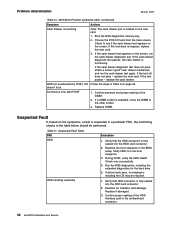
... confirming checks in the table below should be required. 1. Verify that HDD connector is functioning. Replace if damaged. 3. Boot the RSS diagnostics memory key. 2. If the cash drawer test appears on the screen; replace the riser card. Verify that the HDD connector is available, move the...page 32. If above tests pass, re-imaging/reinstalling the OS may be performed. doesn't boot. Problem determination March 2009 Table 10. 4810/4910 Problem symptoms table (continued) Symptom Actions Cash Drawer not working Note: The cash drawer port is in the boot sequence. 3. ...
... confirming checks in the table below should be required. 1. Verify that HDD connector is functioning. Replace if damaged. 3. Boot the RSS diagnostics memory key. 2. If the cash drawer test appears on the screen; replace the riser card. Verify that the HDD connector is available, move the...page 32. If above tests pass, re-imaging/reinstalling the OS may be performed. doesn't boot. Problem determination March 2009 Table 10. 4810/4910 Problem symptoms table (continued) Symptom Actions Cash Drawer not working Note: The cash drawer port is in the boot sequence. 3. ...

Installation Guide
Page 49
Does the system unit test identify the modular flash drive as follow: v Riser v Power Connector v Power switch card cable v Memory v HDD Assembly Note: Disconnect all external cables and reconnect one at the power outlet. 2. No - Does the test pass? System Board 1. Power ...ON completely after each device connection to determine if a device is installed properly. 2. Memory Module Run the RSS system unit diagnostic tests. Re-seat the power cord in the questionable USB port. Re-seat the 2 power supply cables inside...
Does the system unit test identify the modular flash drive as follow: v Riser v Power Connector v Power switch card cable v Memory v HDD Assembly Note: Disconnect all external cables and reconnect one at the power outlet. 2. No - Does the test pass? System Board 1. Power ...ON completely after each device connection to determine if a device is installed properly. 2. Memory Module Run the RSS system unit diagnostic tests. Re-seat the power cord in the questionable USB port. Re-seat the 2 power supply cables inside...

Installation Guide
Page 53
...44V2048 - - 41D7062 - 44V2049 - 41D7063 - 44V2050 - 44V2051 - 44V2052 - 44D0158 - 44D0159 - 41D0403 - 41D7087 - 44V2053 Assembly 1: (continued) Units Description 4810/4910 System Unit Assembly 1 Top cover 1 Power supply 1 Riser card assembly 1 I/O Connector card latch 1 SurePort Serial Connector card (RS232) 1 SurePort USB ...Connector card 1 Hard-disk drive card/tray assembly 1 Hard-disk drive, 160 GB 1 Memory module, 0.5 GB 1 Memory module, 1 GB 1 Modular flash drive, 4 GB 1 Battery, coin cell (CR2032) 1 System board (planar) 1 Hard...
...44V2048 - - 41D7062 - 44V2049 - 41D7063 - 44V2050 - 44V2051 - 44V2052 - 44D0158 - 44D0159 - 41D0403 - 41D7087 - 44V2053 Assembly 1: (continued) Units Description 4810/4910 System Unit Assembly 1 Top cover 1 Power supply 1 Riser card assembly 1 I/O Connector card latch 1 SurePort Serial Connector card (RS232) 1 SurePort USB ...Connector card 1 Hard-disk drive card/tray assembly 1 Hard-disk drive, 160 GB 1 Memory module, 0.5 GB 1 Memory module, 1 GB 1 Modular flash drive, 4 GB 1 Battery, coin cell (CR2032) 1 System board (planar) 1 Hard...
Installation Guide
Page 81
... Canada 60 Japan 61 Korea 61 Taiwan 62 electrostatic discharge (ESD) 62 end of life disposal 63 equipment disposal 63 © Copyright IBM Corp. 2005, 2009 F features, model 1 ferrite requirement 62 flash drive removal 16 flat panel displays 66 front cover removal 27 front...61 Japanese Voluntary Control Council for Interference statement 61 jumper, CMOS 23 K Korean communications statement 61 L LED indicators 4 M memory key setup 29 memory keys 29 memory module removal 17 mercury-added statement 66 model features 1 N notices 51, 57 battery recycling 64 cable ferrites 62 electronic emissions...
... Canada 60 Japan 61 Korea 61 Taiwan 62 electrostatic discharge (ESD) 62 end of life disposal 63 equipment disposal 63 © Copyright IBM Corp. 2005, 2009 F features, model 1 ferrite requirement 62 flash drive removal 16 flat panel displays 66 front cover removal 27 front...61 Japanese Voluntary Control Council for Interference statement 61 jumper, CMOS 23 K Korean communications statement 61 L LED indicators 4 M memory key setup 29 memory keys 29 memory module removal 17 mercury-added statement 66 model features 1 N notices 51, 57 battery recycling 64 cable ferrites 62 electronic emissions...

Installation Guide
Page 82
... 16 front cover 27 front-panel card 18 hard disk drive 14 hard disk drive air duct 22 hard drive assembly 15 I/O connector card 19 memory module 17 power supply 21 riser and I/O card assembly 20 system board 25 top cover 12 riser card and I/O assembly removal 20 S safety information 51...
... 16 front cover 27 front-panel card 18 hard disk drive 14 hard disk drive air duct 22 hard drive assembly 15 I/O connector card 19 memory module 17 power supply 21 riser and I/O card assembly 20 system board 25 top cover 12 riser card and I/O assembly removal 20 S safety information 51...