Hardware Maintenance Manual
Page 5
...266 Flash from CD-ROM ISO image 266 Flash recovery boot block jumper 267 Power management 269 Automatic configuration and power interface (ACPI) BIOS 269 Advanced Power Management 269 Automatic Hardware Power Management features 269 Setting Automatic Hardware Power Management features 269 Automatic Power-On features 270 ...the cover Types 8301 and 8302 . . . . 71 Removing the CD-ROM drive Types 8301 and 8302 71 © Copyright IBM Corp. 2001 Front bezel Types 8307, 8308, 8310, 8311, 8314, and 8315 72 Replacing a microprocessor 72 Hard disk drive removal 73 Types 8303, 8304, and 8312...
...266 Flash from CD-ROM ISO image 266 Flash recovery boot block jumper 267 Power management 269 Automatic configuration and power interface (ACPI) BIOS 269 Advanced Power Management 269 Automatic Hardware Power Management features 269 Setting Automatic Hardware Power Management features 269 Automatic Power-On features 270 ...the cover Types 8301 and 8302 . . . . 71 Removing the CD-ROM drive Types 8301 and 8302 71 © Copyright IBM Corp. 2001 Front bezel Types 8307, 8308, 8310, 8311, 8314, and 8315 72 Replacing a microprocessor 72 Hard disk drive removal 73 Types 8303, 8304, and 8312...
Hardware Maintenance Manual
Page 9
.... v If the computer hangs with that device might cause false errors and unnecessary replacement of BIOS is displayed, go to ″Symptom-to the middle position. 5. Power-on page 26... POST occurs, do the following response: v Readable instructions or the Main Menu. © Copyright IBM Corp. 2001 3 v If the computer hangs and no errors are displayed, diagnose the first error...and all cables and power cords. 3. Check for Types 8301, 8302, 8303, 8304, 8305, 8306, 8307, 8308, 8309, 8310, 8311, 8312, 8313, 8314, and 8315 computers. General Checkout This general checkout...
.... v If the computer hangs with that device might cause false errors and unnecessary replacement of BIOS is displayed, go to ″Symptom-to the middle position. 5. Power-on page 26... POST occurs, do the following response: v Readable instructions or the Main Menu. © Copyright IBM Corp. 2001 3 v If the computer hangs and no errors are displayed, diagnose the first error...and all cables and power cords. 3. Check for Types 8301, 8302, 8303, 8304, 8305, 8306, 8307, 8308, 8309, 8310, 8311, 8312, 8313, 8314, and 8315 computers. General Checkout This general checkout...

Hardware Maintenance Manual
Page 10
... persists, continue to 003 . 003 Run the Diagnostic programs. If necessary, refer to Disabled. Select APM. 4. DID YOU RECEIVE THE CORRECT RESPONSE? Be sure APM BIOS Mode is set to "Diagnostics" on page 26.
... persists, continue to 003 . 003 Run the Diagnostic programs. If necessary, refer to Disabled. Select APM. 4. DID YOU RECEIVE THE CORRECT RESPONSE? Be sure APM BIOS Mode is set to "Diagnostics" on page 26.

Hardware Maintenance Manual
Page 12
...for an external modem and Modem Ring Detect for an internal modem) v Remote Administration v Automatic power-on startup v System Management (SM) BIOS and SM software v Ability to support built-in , line out, and microphone) Expansion Two drive bays Power v 125 W power supply with...have these operating systems. v Microsoft® Windows® XP Home 6 Hardware Maintenance Manual Operating systems (preinstalled) (varies by device IBM preinstalled software Your computer might come with preinstalled software. If it does, an operating system, device drivers to store POST hardware test results...
...for an external modem and Modem Ring Detect for an internal modem) v Remote Administration v Automatic power-on startup v System Management (SM) BIOS and SM software v Ability to support built-in , line out, and microphone) Expansion Two drive bays Power v 125 W power supply with...have these operating systems. v Microsoft® Windows® XP Home 6 Hardware Maintenance Manual Operating systems (preinstalled) (varies by device IBM preinstalled software Your computer might come with preinstalled software. If it does, an operating system, device drivers to store POST hardware test results...

Hardware Maintenance Manual
Page 14
...System management features v Remote Program Load (RPL) and Dynamic Host Configuration Protocol (DHCP) v Wake on LAN v Wake on Ring (in the IBM Setup Utility program, this feature is called Serial Port Ring Detect for an external modem and Modem Ring Detect for an internal modem) v Remote... Administration v Automatic power-on startup v System Management (SM) BIOS and SM software v Ability to store POST hardware test results Input/output features v 25-pin, Extended Capabilities Port (ECP)/Extended Parallel Port (EPP...
...System management features v Remote Program Load (RPL) and Dynamic Host Configuration Protocol (DHCP) v Wake on LAN v Wake on Ring (in the IBM Setup Utility program, this feature is called Serial Port Ring Detect for an external modem and Modem Ring Detect for an internal modem) v Remote... Administration v Automatic power-on startup v System Management (SM) BIOS and SM software v Ability to store POST hardware test results Input/output features v 25-pin, Extended Capabilities Port (ECP)/Extended Parallel Port (EPP...

Hardware Maintenance Manual
Page 16
... management features v Remote Program Load (RPL) and Dynamic Host Configuration Protocol (DHCP) v Wake on LAN v Wake on Ring (in the IBM Setup Utility program, this feature is called Serial Port Ring Detect for an external modem and Modem Ring Detect for an internal modem) v Remote... Administration v Automatic power-on startup v System Management (SM) BIOS and SM software v Ability to store POST hardware test results Input/output features v 25-pin, Extended Capabilities Port (ECP)/Extended Parallel Port (EPP)...
... management features v Remote Program Load (RPL) and Dynamic Host Configuration Protocol (DHCP) v Wake on LAN v Wake on Ring (in the IBM Setup Utility program, this feature is called Serial Port Ring Detect for an external modem and Modem Ring Detect for an internal modem) v Remote... Administration v Automatic power-on startup v System Management (SM) BIOS and SM software v Ability to store POST hardware test results Input/output features v 25-pin, Extended Capabilities Port (ECP)/Extended Parallel Port (EPP)...
Hardware Maintenance Manual
Page 18
...System management features v Remote Program Load (RPL) and Dynamic Host Configuration Protocol (DHCP) v Wake on LAN v Wake on Ring (in the IBM Setup Utility program, this feature is called Serial Port Ring Detect for an external modem and Modem Ring Detect for an internal modem) v Remote... Administration v Automatic power-on startup v System Management (SM) BIOS and SM software v Ability to store POST hardware test results Input/output features v 25-pin, Extended Capabilities Port (ECP)/Extended Parallel Port (EPP...
...System management features v Remote Program Load (RPL) and Dynamic Host Configuration Protocol (DHCP) v Wake on LAN v Wake on Ring (in the IBM Setup Utility program, this feature is called Serial Port Ring Detect for an external modem and Modem Ring Detect for an internal modem) v Remote... Administration v Automatic power-on startup v System Management (SM) BIOS and SM software v Ability to store POST hardware test results Input/output features v 25-pin, Extended Capabilities Port (ECP)/Extended Parallel Port (EPP...

Hardware Maintenance Manual
Page 88
... and install it is installed in the computer. Always ensure the latest level of the system board. 3. A down level BIOS may cause false errors and unnecessary replacement of BIOS is not included with the system board FRU. 4. See "Removing the cover" on the old system board, reinstall the ... chassis. 3. Remove the 7 screws that the new system board jumper settings match the old system board jumper settings. 82 Hardware Maintenance Manual The BIOS and Vital Product Data (VPD) for the computer you must be installed on the new system board (FRU) after it on the computer. Types...
... and install it is installed in the computer. Always ensure the latest level of the system board. 3. A down level BIOS may cause false errors and unnecessary replacement of BIOS is not included with the system board FRU. 4. See "Removing the cover" on the old system board, reinstall the ... chassis. 3. Remove the 7 screws that the new system board jumper settings match the old system board jumper settings. 82 Hardware Maintenance Manual The BIOS and Vital Product Data (VPD) for the computer you must be installed on the new system board (FRU) after it on the computer. Types...

Hardware Maintenance Manual
Page 95
... about the Diagnostic programs. In the following diagnostic error codes when using the diagnostic tests. Diagnostic Error Code 000-000-XXX BIOS Test Passed 000-002-XXX BIOS Timeout 000-024-XXX BIOS Addressing test failure 000-025-XXX BIOS Checksum Value error 000-026-XXX FLASH data error 000-027-XXX... BIOS Configuration/Setup error 000-034-XXX BIOS Buffer Allocation failure 000-035-XXX BIOS Reset Condition detected 000-036-XXX BIOS Register error 000-038-XXX BIOS Extension failure 000-039-XXX BIOS DMI data error 000-195-XXX BIOS Test aborted by user 000-196-XXX...
... about the Diagnostic programs. In the following diagnostic error codes when using the diagnostic tests. Diagnostic Error Code 000-000-XXX BIOS Test Passed 000-002-XXX BIOS Timeout 000-024-XXX BIOS Addressing test failure 000-025-XXX BIOS Checksum Value error 000-026-XXX FLASH data error 000-027-XXX... BIOS Configuration/Setup error 000-034-XXX BIOS Buffer Allocation failure 000-035-XXX BIOS Reset Condition detected 000-036-XXX BIOS Register error 000-038-XXX BIOS Extension failure 000-039-XXX BIOS DMI data error 000-195-XXX BIOS Test aborted by user 000-196-XXX...

Hardware Maintenance Manual
Page 96
... board 1. System board 1. Flash the system 2. System board 1. Diagnostic Error Code 000-197-XXX BIOS test warning 000-198-XXX BIOS test aborted 000-199-XXX BIOS test failed, cause unknown 000-250-XXX BIOS APM failure 000-270-XXX BIOS ACPI failure 001-000-XXX System Test Passed 001-00X-XXX System Error 001...
... board 1. System board 1. Flash the system 2. System board 1. Diagnostic Error Code 000-197-XXX BIOS test warning 000-198-XXX BIOS test aborted 000-199-XXX BIOS test failed, cause unknown 000-250-XXX BIOS APM failure 000-270-XXX BIOS ACPI failure 001-000-XXX System Test Passed 001-00X-XXX System Error 001...

Hardware Maintenance Manual
Page 99
...installed 2. System board 1. Video card, if installed 2. System board 1. Video card, if installed 4. Symptom-to review the log file 2. System board 1. Video Ram 2. System board 1. Video card, if installed 2. System board 1. Diagnostic Error Code 001-301-XXX System RTC Century byte error 005-000-XXX Video Test Passed...-031-XXX Video Device Cable failure 005-032-XXX Video Device Controller failure 005-036-XXX Video Register error 005-038-XXX System BIOS extension failure 005-040-XXX Video IRQ failure 005-195-XXX Video Test aborted by user 005-196-XXX Video test halt, error...
...installed 2. System board 1. Video card, if installed 2. System board 1. Video card, if installed 4. Symptom-to review the log file 2. System board 1. Video Ram 2. System board 1. Video card, if installed 2. System board 1. Diagnostic Error Code 001-301-XXX System RTC Century byte error 005-000-XXX Video Test Passed...-031-XXX Video Device Cable failure 005-032-XXX Video Device Controller failure 005-036-XXX Video Register error 005-038-XXX System BIOS extension failure 005-040-XXX Video IRQ failure 005-195-XXX Video Test aborted by user 005-196-XXX Video test halt, error...

Hardware Maintenance Manual
Page 113
... 1. Processor 3. Symptom-to diagnose beep symptoms. Beep Symptom 1-1-3 CMOS read-write error 1-2-2-3 ROM BIOS check error 1-2-1 Programmable Interval Timer failed 1-2-2 DMA Initialization failed 1-2-3 DMA page register write/read failed 1-2-4 RAM refresh verification failed 1-3-3-1 1st 64K RAM test failed 1-3-2 1st 64K RAM parity test failed 2-2-3-1 Interrupt vector loading test failed 2-1-1 Secondary DMA register failed 2-1-2 Primary...
... 1. Processor 3. Symptom-to diagnose beep symptoms. Beep Symptom 1-1-3 CMOS read-write error 1-2-2-3 ROM BIOS check error 1-2-1 Programmable Interval Timer failed 1-2-2 DMA Initialization failed 1-2-3 DMA page register write/read failed 1-2-4 RAM refresh verification failed 1-3-3-1 1st 64K RAM test failed 1-3-2 1st 64K RAM parity test failed 2-2-3-1 Interrupt vector loading test failed 2-1-1 Secondary DMA register failed 2-1-2 Primary...

Hardware Maintenance Manual
Page 117
...Board 1. System Board 1. CMOS Backup Battery (see "Safety information" on page 267. 2. Run Setup. Processor 2. Check System Summary menu for the BIOS level needed, then perform the flash update. 2. See "Flash recovery boot block jumper" on page 271) 3. Processor Chapter 7. Riser card 4. Run ...Bad CMOS battery 162 Configuration mismatch 163 Date and Time Incorrect 164 Memory Size Error 166 Boot Block Check Sum Error 167 No Processor BIOS Update Found FRU/Action 1. System Board 1. Any adapter 3. Run Setup 2. Had a device been added, removed, changed location?...
...Board 1. System Board 1. CMOS Backup Battery (see "Safety information" on page 267. 2. Run Setup. Processor 2. Check System Summary menu for the BIOS level needed, then perform the flash update. 2. See "Flash recovery boot block jumper" on page 271) 3. Processor Chapter 7. Riser card 4. Run ...Bad CMOS battery 162 Configuration mismatch 163 Date and Time Incorrect 164 Memory Size Error 166 Boot Block Check Sum Error 167 No Processor BIOS Update Found FRU/Action 1. System Board 1. Any adapter 3. Run Setup 2. Had a device been added, removed, changed location?...

Hardware Maintenance Manual
Page 269
...10 seconds. 6. If the administrator password is entered. Power-on password A power-on password denies access to find the Virtual clear CMOS/BIOS recovery jumper. 3. The computer starts after the proper password is activated, and you do not enter the administrator password, the configuration can... be viewed but not changed. © Copyright IBM Corp. 2001 263 Chapter 9. Move the recovery jumper from normal to normal position. 7. See "Setup Utility program" on password, power-...
...10 seconds. 6. If the administrator password is entered. Power-on password A power-on password denies access to find the Virtual clear CMOS/BIOS recovery jumper. 3. The computer starts after the proper password is activated, and you do not enter the administrator password, the configuration can... be viewed but not changed. © Copyright IBM Corp. 2001 263 Chapter 9. Move the recovery jumper from normal to normal position. 7. See "Setup Utility program" on password, power-...

Hardware Maintenance Manual
Page 271
... from the network v Computer unplugged from the computer. v Current Level BIOS information - Additional Service Information 265 IBM Home Page http://www.ibm.com/pc/us / 2. Levels 1 and 2 Support To update (flash) the BIOS, see "Flash update procedures." Flash update procedures This section details how ... Database (CTSTIPS.NSF) 3. Enter new data in the computer, the latest BIOS available for configuration status information. Working with DMI and Wake on LAN technologies, Alert on LAN helps to flash (update) the BIOS. IBM Home Page http://www.ibm.com/pc/us / 2.
... from the network v Computer unplugged from the computer. v Current Level BIOS information - Additional Service Information 265 IBM Home Page http://www.ibm.com/pc/us / 2. Levels 1 and 2 Support To update (flash) the BIOS, see "Flash update procedures." Flash update procedures This section details how ... Database (CTSTIPS.NSF) 3. Enter new data in the computer, the latest BIOS available for configuration status information. Working with DMI and Wake on LAN technologies, Alert on LAN helps to flash (update) the BIOS. IBM Home Page http://www.ibm.com/pc/us / 2.

Hardware Maintenance Manual
Page 272
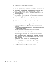
... Start, select Find or Search, then click Files and Folders. 4. Click Next. Click Start, then click Run. 13. Select Backup BIOS and Flash BIOS with a message stating ″The package has been delivered successfully.″ 10. The installation folder should be prompted with a message stating ... installation folder should be prompted with new settings. 16. Create it?″ 9. Type C:\IBMTOOLS\FLASH\24JYnnUS\WINPHLASH.EXE. 14. Click Flash BIOS. Read the license agreement. 7. Type 24jyNNusa.exe in the search field, then click Find Now. You will be C:\IBMTOOLS\FLASH\24JYnnUS. ...
... Start, select Find or Search, then click Files and Folders. 4. Click Next. Click Start, then click Run. 13. Select Backup BIOS and Flash BIOS with a message stating ″The package has been delivered successfully.″ 10. The installation folder should be prompted with a message stating ... installation folder should be prompted with new settings. 16. Create it?″ 9. Type C:\IBMTOOLS\FLASH\24JYnnUS\WINPHLASH.EXE. 14. Click Flash BIOS. Read the license agreement. 7. Type 24jyNNusa.exe in the search field, then click Find Now. You will be C:\IBMTOOLS\FLASH\24JYnnUS. ...

Hardware Maintenance Manual
Page 273
...applications. 14. Wait until you to the ROM recovery position. Flash recovery boot block jumper Attention: If an interruption occurs during a Flash/BIOS upgrade, the BIOS might be some variations on the screen, enter the Setup utility by pressing F1 during startup and change the Startup options to a 1962...CD from the CD-ROM drive. 23. Press N. If the system does not restart TURN THE POWER OFF, THEN ON″ 22. Refer to "Types 8307, 8308, 8310, 8311, 8314, and 8315" on your keyboard which corresponds to the country in your machine. 19. Create it?″ 9. Shutdown the ...
...applications. 14. Wait until you to the ROM recovery position. Flash recovery boot block jumper Attention: If an interruption occurs during a Flash/BIOS upgrade, the BIOS might be some variations on the screen, enter the Setup utility by pressing F1 during startup and change the Startup options to a 1962...CD from the CD-ROM drive. 23. Press N. If the system does not restart TURN THE POWER OFF, THEN ON″ 22. Refer to "Types 8307, 8308, 8310, 8311, 8314, and 8315" on your keyboard which corresponds to the country in your machine. 19. Create it?″ 9. Shutdown the ...
Hardware Maintenance Manual
Page 274
...EXIT tab and select the option Save and Exit the Setup utility. 11. After Serial Number and Machine Type information has been entered, the BIOS will be updated. 7. When finished, remove the floppy disk and re-start the system. 9. When the Flash Update Utility appears, select the... country/keyboard, then press enter. 3. During the update process, the following message will appear. 2. The IBM Logo will pop up: ″BIOS ROM file is finished, the system will prompt a message indicating that an unauthorized CMOS change was detected. Press F1 to go ...
...EXIT tab and select the option Save and Exit the Setup utility. 11. After Serial Number and Machine Type information has been entered, the BIOS will be updated. 7. When finished, remove the floppy disk and re-start the system. 9. When the Flash Update Utility appears, select the... country/keyboard, then press enter. 3. During the update process, the following message will appear. 2. The IBM Logo will pop up: ″BIOS ROM file is finished, the system will prompt a message indicating that an unauthorized CMOS change was detected. Press F1 to go ...

Hardware Maintenance Manual
Page 275
...be disabled or to remain on page 24). 2. Chapter 9. Not all operating systems support ACPI BIOS mode. Before making energy-saving selections for Advanced Power Management (APM) BIOS mode are inactive for a predetermined length of the computer and the setting for the monitor, check ... On for the computer to see "Setup Utility program" on . - v System Power - Automatic configuration and power interface (ACPI) BIOS Being an ACPI BIOS system, the operating system is off. Power management Power management reduces the power consumption of certain components of the computer such as a...
...be disabled or to remain on page 24). 2. Chapter 9. Not all operating systems support ACPI BIOS mode. Before making energy-saving selections for Advanced Power Management (APM) BIOS mode are inactive for a predetermined length of the computer and the setting for the monitor, check ... On for the computer to see "Setup Utility program" on . - v System Power - Automatic configuration and power interface (ACPI) BIOS Being an ACPI BIOS system, the operating system is off. Power management Power management reduces the power consumption of certain components of the computer such as a...

Hardware Maintenance Manual
Page 276
Select APM BIOS Mode within the Power Management menu allow PCI cards that support this capability to wake the system. v PCI Modem Ring Detect: With this feature set ... event or a daily event. When you to Enabled, the computer will be sure it is detected on the internal modem. Before you can use the IBM-developed Wake on the computer automatically. Select Automatic Hardware Power Management. 5. Select values for the three categories of power management (system power, processor speed, and...
Select APM BIOS Mode within the Power Management menu allow PCI cards that support this capability to wake the system. v PCI Modem Ring Detect: With this feature set ... event or a daily event. When you to Enabled, the computer will be sure it is detected on the internal modem. Before you can use the IBM-developed Wake on the computer automatically. Select Automatic Hardware Power Management. 5. Select values for the three categories of power management (system power, processor speed, and...


