Product Guide
Page 2
... sur le broullage radioélectrique édicté par le ministére des Communications du Canada. The Intel® D815EEA2, D815EPEA2, D815EFV, and D815EPFV desktop boards may cause harmful interference to any interference received, including interference that interference will not ... of any time, without notice. Revision History Revision -001 Revision History First release of the Desktop Boards D815EEA2, D815EPEA2, D815EFV, and D815EPFV Product Guide Intel® Date March 2001 If an FCC declaration of conformity marking is present on request. Canadian Department of...
... sur le broullage radioélectrique édicté par le ministére des Communications du Canada. The Intel® D815EEA2, D815EPEA2, D815EFV, and D815EPFV desktop boards may cause harmful interference to any interference received, including interference that interference will not ... of any time, without notice. Revision History Revision -001 Revision History First release of the Desktop Boards D815EEA2, D815EPEA2, D815EFV, and D815EPFV Product Guide Intel® Date March 2001 If an FCC declaration of conformity marking is present on request. Canadian Department of...
Product Guide
Page 4
Intel Desktop Boards D815EEA2, D815EPEA2, D815EFV, and D815EPFV Product Guide Installing and Removing AGP and GPA Cards ...31 Installing an AGP Card ...31 Removing the AGP Card from the Retention Mechanism ...31 Installing and Removing a GPA Card (D815EEA2 and D815EFV only) ...32 Installing the I/O Shield ...... Fan Heatsink ...39 Removing the 1 GHz Processor Fan Heatsink ...42 Replacing the Battery ...43 Replacing the Battery on the D815EEA2 and D815EPEA2 Boards ...45 Replacing the Battery on the D815EFV and D815EPFV Boards ...46 Connecting the IDE Cable ...47 Setting the BIOS Configuration...
Intel Desktop Boards D815EEA2, D815EPEA2, D815EFV, and D815EPFV Product Guide Installing and Removing AGP and GPA Cards ...31 Installing an AGP Card ...31 Removing the AGP Card from the Retention Mechanism ...31 Installing and Removing a GPA Card (D815EEA2 and D815EFV only) ...32 Installing the I/O Shield ...... Fan Heatsink ...39 Removing the 1 GHz Processor Fan Heatsink ...42 Replacing the Battery ...43 Replacing the Battery on the D815EEA2 and D815EPEA2 Boards ...45 Replacing the Battery on the D815EFV and D815EPFV Boards ...46 Connecting the IDE Cable ...47 Setting the BIOS Configuration...
Product Guide
Page 6
... the Processor Fan Cable to the Processor Fan Connector ...41 Removing the Fan Heatsink...42 Removing the Battery from the D815EEA2 and D815EPEA2 Boards ...45 Removing the Battery from the D815EFV and D815EPFV Boards ...46 Connecting the IDE Cable (the...Summary ...9 Manufacturing Options...11 Supported Processors ...14 Processor and Memory Module Combinations...16 RJ-45 LAN Connector LEDs ...22 Jumper Settings for the D815EEA2 and D815EPEA2 Boards ...83 32. Intel Desktop Boards D815EEA2, D815EPEA2, D815EFV, and D815EPFV Product Guide 16. 17. 18. 19. 20. 21. 22. 23. 24. 25. 26. 27. 28...
... the Processor Fan Cable to the Processor Fan Connector ...41 Removing the Fan Heatsink...42 Removing the Battery from the D815EEA2 and D815EPEA2 Boards ...45 Removing the Battery from the D815EFV and D815EPFV Boards ...46 Connecting the IDE Cable (the...Summary ...9 Manufacturing Options...11 Supported Processors ...14 Processor and Memory Module Combinations...16 RJ-45 LAN Connector LEDs ...22 Jumper Settings for the D815EEA2 and D815EPEA2 Boards ...83 32. Intel Desktop Boards D815EEA2, D815EPEA2, D815EFV, and D815EPFV Product Guide 16. 17. 18. 19. 20. 21. 22. 23. 24. 25. 26. 27. 28...

Product Guide
Page 10
... Feature Summary (continued) Specification • The D815EEA2 and D815EFV boards include: Intel 82815E integrated graphics support AGP universal connector supporting 1x, 2x, or 4x AGP cards or a Graphics Performance Accelerator (GPA) Characteristic Rear panel VGA connector • The D815EPEA2 and D815EPFV boards include an AGP universal connector ... • Two IDE interfaces with Ultra DMA (33 MB/sec) and ATA-66/100 support • One diskette drive interface • PS/2 Intel Desktop Boards D815EEA2, D815EPEA2, D815EFV, and D815EPFV Product Guide Table 2.
... Feature Summary (continued) Specification • The D815EEA2 and D815EFV boards include: Intel 82815E integrated graphics support AGP universal connector supporting 1x, 2x, or 4x AGP cards or a Graphics Performance Accelerator (GPA) Characteristic Rear panel VGA connector • The D815EPEA2 and D815EPFV boards include an AGP universal connector ... • Two IDE interfaces with Ultra DMA (33 MB/sec) and ATA-66/100 support • One diskette drive interface • PS/2 Intel Desktop Boards D815EEA2, D815EPEA2, D815EFV, and D815EPFV Product Guide Table 2.

Product Guide
Page 12
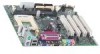
...; Intel 82815E GMCH (D815EEA2 only) • Intel 82815EP MCH (D815EPEA2 only) 370-pin processor socket DIMM sockets Chassis fan connector (fan 3) Speaker Main power connector Diskette drive connector Q R S T U V W X Y Z AA BB CC DD EE Primary IDE connector Secondary IDE connector Intel 82801BA I/O Controller Hub (ICH2) SMSC LPC47M132 I/O controller (optional SMSC LPC47M142 I J K L M N O P CNR connector (optional) Analog Devices Inc. Intel Desktop Boards D815EEA2, D815EPEA2...
...; Intel 82815E GMCH (D815EEA2 only) • Intel 82815EP MCH (D815EPEA2 only) 370-pin processor socket DIMM sockets Chassis fan connector (fan 3) Speaker Main power connector Diskette drive connector Q R S T U V W X Y Z AA BB CC DD EE Primary IDE connector Secondary IDE connector Intel 82801BA I/O Controller Hub (ICH2) SMSC LPC47M132 I/O controller (optional SMSC LPC47M142 I J K L M N O P CNR connector (optional) Analog Devices Inc. Intel Desktop Boards D815EEA2, D815EPEA2...
Product Guide
Page 14
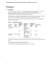
... to the desktop board through a PGA370 socket. The boards support the processors listed in Table 4. Processor Type Intel Pentium III processors Supported Processors Socket Type FC-PGA Processor Frequency (GHz).... Intel Desktop Boards D815EEA2, D815EPEA2, D815EFV, and D815EPFV Product Guide Processors CAUTION Use only the processors listed below. See the Intel Desktop D815EA2/D815EPEA2 or...processor connects to the Intel desktop board Web site at: http://support.intel.com/support/motherboards/desktop/ For instructions on processor support for theD815EEA2, D815EPEA2, D815EFV, and ...
... to the desktop board through a PGA370 socket. The boards support the processors listed in Table 4. Processor Type Intel Pentium III processors Supported Processors Socket Type FC-PGA Processor Frequency (GHz).... Intel Desktop Boards D815EEA2, D815EPEA2, D815EFV, and D815EPFV Product Guide Processors CAUTION Use only the processors listed below. See the Intel Desktop D815EA2/D815EPEA2 or...processor connects to the Intel desktop board Web site at: http://support.intel.com/support/motherboards/desktop/ For instructions on processor support for theD815EEA2, D815EPEA2, D815EFV, and ...

Product Guide
Page 16
... (see note below) Processor Type (System Bus Frequency) Intel Celeron processor (66 MHz) Intel Celeron processor (100 MHz) Intel Pentium III processor (100 MHz) Intel Pentium III processor (133 MHz) ✏ NOTES 100 MHz system bus frequency processors will operate at 100 MHz. Intel Desktop Boards D815EEA2, D815EPEA2, D815EFV, and D815EPFV Product Guide Unbuffered single or double...
... (see note below) Processor Type (System Bus Frequency) Intel Celeron processor (66 MHz) Intel Celeron processor (100 MHz) Intel Pentium III processor (100 MHz) Intel Pentium III processor (133 MHz) ✏ NOTES 100 MHz system bus frequency processors will operate at 100 MHz. Intel Desktop Boards D815EEA2, D815EPEA2, D815EFV, and D815EPFV Product Guide Unbuffered single or double...

Product Guide
Page 18
Intel Desktop Boards D815EEA2, D815EPEA2, D815EFV, and D815EPFV Product Guide Firmware Hub (FWH) The 4 Mbit Firmware Hub has these features: • • System BIOS System security and management logic Input/...
Intel Desktop Boards D815EEA2, D815EPEA2, D815EFV, and D815EPFV Product Guide Firmware Hub (FWH) The 4 Mbit Firmware Hub has these features: • • System BIOS System security and management logic Input/...

Product Guide
Page 20
Intel Desktop Boards D815EEA2, D815EPEA2, D815EFV, and D815EPFV Product Guide Audio Subsystem The boards have an AC '97 compliant audio subsystem. AD1885 analog codec The audio subsystem consists of the ... only. The BIOS is designed to this output. The BIOS can override the autoconfiguration options by following items are available from Intel's World Wide Web site: http://support.intel.com/support/motherboards/desktop BIOS The BIOS provides the Power-On Self-Test (POST), the BIOS Setup program, the PCI and IDE auto-configuration...
Intel Desktop Boards D815EEA2, D815EPEA2, D815EFV, and D815EPFV Product Guide Audio Subsystem The boards have an AC '97 compliant audio subsystem. AD1885 analog codec The audio subsystem consists of the ... only. The BIOS is designed to this output. The BIOS can override the autoconfiguration options by following items are available from Intel's World Wide Web site: http://support.intel.com/support/motherboards/desktop BIOS The BIOS provides the Power-On Self-Test (POST), the BIOS Setup program, the PCI and IDE auto-configuration...

Product Guide
Page 22
...Power management is communicating with an ACPI-aware operating system, the BIOS can provide ACPI support. Otherwise, it defaults to the D815EEA2, D815EPEA2, D815EFV, or D815EPFV link on Intel's World Wide Web site at several levels, including: • Software support: Advanced Power Management (APM) •...powered up and the LAN subsystem is not established. LAN link is operating. The computer is implemented at : http://support.intel.com/support/motherboards/desktop RJ-45 LAN Connector LEDs Two LEDs are built into the RJ-45 LAN connector. LAN link is selected. ...
...Power management is communicating with an ACPI-aware operating system, the BIOS can provide ACPI support. Otherwise, it defaults to the D815EEA2, D815EPEA2, D815EFV, or D815EPFV link on Intel's World Wide Web site at several levels, including: • Software support: Advanced Power Management (APM) •...powered up and the LAN subsystem is not established. LAN link is operating. The computer is implemented at : http://support.intel.com/support/motherboards/desktop RJ-45 LAN Connector LEDs Two LEDs are built into the RJ-45 LAN connector. LAN link is selected. ...
Product Guide
Page 23
... must be capable of providing adequate +5-V standby current. See Figure 30 on the desktop board. For more information about front panel LED states, see the Intel ® Desktop Board D815EEA2/D815EPEA2 Technical Product Specification or Intel ® Desktop Board D815EFV/D815EPFV Technical Product Specification. 23
... must be capable of providing adequate +5-V standby current. See Figure 30 on the desktop board. For more information about front panel LED states, see the Intel ® Desktop Board D815EEA2/D815EPEA2 Technical Product Specification or Intel ® Desktop Board D815EFV/D815EPFV Technical Product Specification. 23

Product Guide
Page 24
... 1.5 A of Resume on Ring can be unmasked for more information. Intel Desktop Boards D815EEA2, D815EPEA2, D815EFV, and D815EPFV Product Guide CR6F1 STR LED OM11632 Figure 3. Location of Standby Power Indicator (the D815EEA2 Board Is Shown) CAUTION Power supplies used with the board must provide ...from either the APM sleep mode or the ACPI S1 state Requires only one call to the Intel Desktop Board D815EEA2/D815EPEA2 Technical Product Specification or Intel Desktop Board D815EFV/D815EPFV Technical Product Specification for correct operation 24 If the standby current necessary to ...
... 1.5 A of Resume on Ring can be unmasked for more information. Intel Desktop Boards D815EEA2, D815EPEA2, D815EFV, and D815EPFV Product Guide CR6F1 STR LED OM11632 Figure 3. Location of Standby Power Indicator (the D815EEA2 Board Is Shown) CAUTION Power supplies used with the board must provide ...from either the APM sleep mode or the ACPI S1 state Requires only one call to the Intel Desktop Board D815EEA2/D815EPEA2 Technical Product Specification or Intel Desktop Board D815EFV/D815EPFV Technical Product Specification for correct operation 24 If the standby current necessary to ...

Product Guide
Page 26
... access the PC Serial Presence Detect Specification at : http://www.intel.com/technology/memory/pcsdram/spec/ Installing DIMMs To install DIMMs, follow these steps: 1. Intel Desktop Boards D815EEA2, D815EPEA2, D815EFV, and D815EPFV Product Guide Installing and Removing Memory CAUTION Install memory in the DIMM sockets prior to installing the AGP video card to the computer...
... access the PC Serial Presence Detect Specification at : http://www.intel.com/technology/memory/pcsdram/spec/ Installing DIMMs To install DIMMs, follow these steps: 1. Intel Desktop Boards D815EEA2, D815EPEA2, D815EFV, and D815EPFV Product Guide Installing and Removing Memory CAUTION Install memory in the DIMM sockets prior to installing the AGP video card to the computer...

Product Guide
Page 28
... CAUTION Install the retention mechanism (RM) only when using a card with an unnotched card may impair operation. If you need to installed cards. 28 Intel Desktop Boards D815EEA2, D815EPEA2, D815EFV, and D815EPFV Product Guide Installing and Removing the AGP Card Retention Mechanism The AGP universal connector supports AGP (1x, 2x, and 4x) and...
... CAUTION Install the retention mechanism (RM) only when using a card with an unnotched card may impair operation. If you need to installed cards. 28 Intel Desktop Boards D815EEA2, D815EPEA2, D815EFV, and D815EPFV Product Guide Installing and Removing the AGP Card Retention Mechanism The AGP universal connector supports AGP (1x, 2x, and 4x) and...

Product Guide
Page 30
... (see Figure 7): 1. Removing the AGP Card Retention Mechanism 30 Spread the sides of the retention mechanism (C) and lift the retention mechanism off the board. Intel Desktop Boards D815EEA2, D815EPEA2, D815EFV, and D815EPFV Product Guide Removing the AGP Card Retention Mechanism The removal instructions below are for AGP card retention mechanisms that cannot easily...
... (see Figure 7): 1. Removing the AGP Card Retention Mechanism 30 Spread the sides of the retention mechanism (C) and lift the retention mechanism off the board. Intel Desktop Boards D815EEA2, D815EPEA2, D815EFV, and D815EPFV Product Guide Removing the AGP Card Retention Mechanism The removal instructions below are for AGP card retention mechanisms that cannot easily...

Product Guide
Page 32
... in direction (G) to the pins of the computer. Using Figure 9 as the card is maintained in direction (D). A C B D F E F G OM10410 Figure 9. Intel Desktop Boards D815EEA2, D815EPEA2, D815EFV, and D815EPFV Product Guide Installing and Removing a GPA Card (D815EEA2 and D815EFV only) CAUTION Remove the GPA video card before inserting. Position the GPA card over the AGP connector...
... in direction (G) to the pins of the computer. Using Figure 9 as the card is maintained in direction (D). A C B D F E F G OM10410 Figure 9. Intel Desktop Boards D815EEA2, D815EPEA2, D815EFV, and D815EPFV Product Guide Installing and Removing a GPA Card (D815EEA2 and D815EFV only) CAUTION Remove the GPA video card before inserting. Position the GPA card over the AGP connector...

Product Guide
Page 34
Intel Desktop Boards D815EEA2, D815EPEA2, D815EFV, and D815EPFV Product Guide Installing the Desktop Board Refer to your chassis manual for regulatory requirements and installation instructions and precautions. Disconnect the computer ... qualified technical personnel should attempt this procedure. OM11625 Figure 11. Refer to disconnect the power before performing the procedures described here. Seven screws for the D815EEA2 and D815EPEA2 boards and six screws for the...
Intel Desktop Boards D815EEA2, D815EPEA2, D815EFV, and D815EPFV Product Guide Installing the Desktop Board Refer to your chassis manual for regulatory requirements and installation instructions and precautions. Disconnect the computer ... qualified technical personnel should attempt this procedure. OM11625 Figure 11. Refer to disconnect the power before performing the procedures described here. Seven screws for the D815EEA2 and D815EPEA2 boards and six screws for the...

Product Guide
Page 36
Close the handle completely (see Figure 13, A and C). 4. Aligning the pins of the processor with the socket, insert the processor into the socket (see Figure 13, D). Intel Desktop Boards D815EEA2, D815EPEA2, D815EFV, and D815EPFV Product Guide Installing a Processor To install a processor, follow these instructions: 1. B C A D OM11639 Figure 13. Installing the Processor in "Before You Begin" (see Figure 13, B). 3. Observe the precautions in the Processor Socket 36 Locate the processor socket and raise the socket handle completely (see page 25). 2.
Close the handle completely (see Figure 13, A and C). 4. Aligning the pins of the processor with the socket, insert the processor into the socket (see Figure 13, D). Intel Desktop Boards D815EEA2, D815EPEA2, D815EFV, and D815EPFV Product Guide Installing a Processor To install a processor, follow these instructions: 1. B C A D OM11639 Figure 13. Installing the Processor in "Before You Begin" (see Figure 13, B). 3. Observe the precautions in the Processor Socket 36 Locate the processor socket and raise the socket handle completely (see page 25). 2.

Product Guide
Page 38
... page 25). 2. Detach the fan heatsink clips. 4. Remove the heatsink. 5. Remove the processor. 38 J1B1 J1B1 A PG 37 0 OM11156 Figure 16. Raise the socket handle completely. 6. Intel Desktop Boards D815EEA2, D815EPEA2, D815EFV, and D815EPFV Product Guide 7. Observe the precautions in "Before You Begin" (see Figure 16). Disconnect the processor fan cable. 3. Connect the processor...
... page 25). 2. Detach the fan heatsink clips. 4. Remove the heatsink. 5. Remove the processor. 38 J1B1 J1B1 A PG 37 0 OM11156 Figure 16. Raise the socket handle completely. 6. Intel Desktop Boards D815EEA2, D815EPEA2, D815EFV, and D815EPFV Product Guide 7. Observe the precautions in "Before You Begin" (see Figure 16). Disconnect the processor fan cable. 3. Connect the processor...

Product Guide
Page 40
When properly aligned, each edge of the plastic clip should click into place. Lowering the Plastic Clip Handle 40 Hold the clip handle (see Figure 19, A) and very slowly lower the handle until the clip secures the fan heatsink to the processor socket. Intel Desktop Boards D815EEA2, D815EPEA2, D815EFV, and D815EPFV Product Guide 3. A B OM11062 Figure 19.
When properly aligned, each edge of the plastic clip should click into place. Lowering the Plastic Clip Handle 40 Hold the clip handle (see Figure 19, A) and very slowly lower the handle until the clip secures the fan heatsink to the processor socket. Intel Desktop Boards D815EEA2, D815EPEA2, D815EFV, and D815EPFV Product Guide 3. A B OM11062 Figure 19.