Product Guide
Page 4
...1 GHz Processor Fan Heatsink ...39 Removing the 1 GHz Processor Fan Heatsink ...42 Replacing the Battery ...43 Replacing the Battery on the D815EEA2 and D815EPEA2 Boards ...45 Replacing the Battery on the D815EFV and D815EPFV Boards ...46 Connecting the IDE Cable ...47 Setting the BIOS Configuration ...Jumper...48 Clearing the Passwords...49 3 Updating the BIOS Updating the BIOS with the Intel® Express BIOS Update Utility ...51 Updating the BIOS with the Intel® Flash Memory Update Utility ...51 Preparing for the Update ...51 Obtaining the BIOS Update File ...52 Saving...
...1 GHz Processor Fan Heatsink ...39 Removing the 1 GHz Processor Fan Heatsink ...42 Replacing the Battery ...43 Replacing the Battery on the D815EEA2 and D815EPEA2 Boards ...45 Replacing the Battery on the D815EFV and D815EPFV Boards ...46 Connecting the IDE Cable ...47 Setting the BIOS Configuration ...Jumper...48 Clearing the Passwords...49 3 Updating the BIOS Updating the BIOS with the Intel® Express BIOS Update Utility ...51 Updating the BIOS with the Intel® Flash Memory Update Utility ...51 Preparing for the Update ...51 Obtaining the BIOS Update File ...52 Saving...
Product Guide
Page 6
... the Processor Fan Cable to the Processor Fan Connector ...41 Removing the Fan Heatsink...42 Removing the Battery from the D815EEA2 and D815EPEA2 Boards ...45 Removing the Battery from the D815EFV and D815EPFV Boards ...46 Connecting the IDE Cable (the...vi Board Differences ...9 Feature Summary ...9 Manufacturing Options...11 Supported Processors ...14 Processor and Memory Module Combinations...16 RJ-45 LAN Connector LEDs ...22 Jumper Settings for the D815EFV and D815EPFV Boards...84 33. Intel Desktop Boards D815EEA2, D815EPEA2, D815EFV, and D815EPFV Product Guide 16. 17. 18. 19. 20. 21...
... the Processor Fan Cable to the Processor Fan Connector ...41 Removing the Fan Heatsink...42 Removing the Battery from the D815EEA2 and D815EPEA2 Boards ...45 Removing the Battery from the D815EFV and D815EPFV Boards ...46 Connecting the IDE Cable (the...vi Board Differences ...9 Feature Summary ...9 Manufacturing Options...11 Supported Processors ...14 Processor and Memory Module Combinations...16 RJ-45 LAN Connector LEDs ...22 Jumper Settings for the D815EFV and D815EPFV Boards...84 33. Intel Desktop Boards D815EEA2, D815EPEA2, D815EFV, and D815EPFV Product Guide 16. 17. 18. 19. 20. 21...

Product Guide
Page 9
... 2. Table 1. Feature Summary Specification • ATX at 11.55 inches by 8.20 inches (D815EEA2 and D815EPEA2) • microATX at 9.6 inches by 8.2 inches (D815EFV and D815EPFV) Processors • Intel® Pentium® III processor family with ...Memory Module (DIMM) sockets supporting: • 100 MHz PC100 SDRAM (all system bus frequencies) • 133 MHz PC133 SDRAM (only with 133 MHz system bus frequency processors) Chipsets • The D815EEA2 and D815EFV boards include the Intel 815E Chipset, consisting of: Intel 82815E Graphics Memory Controller Hub (GMCH) Intel...
... 2. Table 1. Feature Summary Specification • ATX at 11.55 inches by 8.20 inches (D815EEA2 and D815EPEA2) • microATX at 9.6 inches by 8.2 inches (D815EFV and D815EPFV) Processors • Intel® Pentium® III processor family with ...Memory Module (DIMM) sockets supporting: • 100 MHz PC100 SDRAM (all system bus frequencies) • 133 MHz PC133 SDRAM (only with 133 MHz system bus frequency processors) Chipsets • The D815EEA2 and D815EFV boards include the Intel 815E Chipset, consisting of: Intel 82815E Graphics Memory Controller Hub (GMCH) Intel...

Product Guide
Page 16
... MHz ...will operate at 100 MHz ...will operate at 100 MHz. Intel Desktop Boards D815EEA2, D815EPEA2, D815EFV, and D815EPFV Product Guide Unbuffered single or double-sided DIMMs Serial Presence Detect (SPD) memory Non-ECC and ECC DIMMs (ECC DIMMs will operate in Table 5. ...If more than four sides are used ; however, the memory will support 133 MHz memory; Chipsets The D815EEA2 and D815EFV boards include the following chipset Intel 82815E Graphics Memory Controller Hub (GMCH) with Accelerated Hub Architecture (AHA) bus Intel 82801BA I/O Controller Hub (ICH2) with AHA bus 4 Mbit...
... MHz ...will operate at 100 MHz ...will operate at 100 MHz. Intel Desktop Boards D815EEA2, D815EPEA2, D815EFV, and D815EPFV Product Guide Unbuffered single or double-sided DIMMs Serial Presence Detect (SPD) memory Non-ECC and ECC DIMMs (ECC DIMMs will operate in Table 5. ...If more than four sides are used ; however, the memory will support 133 MHz memory; Chipsets The D815EEA2 and D815EFV boards include the following chipset Intel 82815E Graphics Memory Controller Hub (GMCH) with Accelerated Hub Architecture (AHA) bus Intel 82801BA I/O Controller Hub (ICH2) with AHA bus 4 Mbit...

Product Guide
Page 17
..., or TV-out Support for ACPI Rev 2.0 and APM Rev 1.2 compliant power management Intel® 82815EP Memory Controller Hub (MCH) The MCH provides the following An integrated Synchronous DRAM memory controller with autodetection of SDRAM An interface for a single AGP device Support for ACPI Rev... compliant power management Intel® 82801BA I/O Controller Hub (ICH2) The Intel 82801BA ICH2 has these features: • 33 MHz Peripheral Component Interface (PCI) Local Bus slots supporting PCI specification, rev 2.2: Four PCI plus one PCI/CNR shared connector (D815EEA2 Two PCI plus one...
..., or TV-out Support for ACPI Rev 2.0 and APM Rev 1.2 compliant power management Intel® 82815EP Memory Controller Hub (MCH) The MCH provides the following An integrated Synchronous DRAM memory controller with autodetection of SDRAM An interface for a single AGP device Support for ACPI Rev... compliant power management Intel® 82801BA I/O Controller Hub (ICH2) The Intel 82801BA ICH2 has these features: • 33 MHz Peripheral Component Interface (PCI) Local Bus slots supporting PCI specification, rev 2.2: Four PCI plus one PCI/CNR shared connector (D815EEA2 Two PCI plus one...
Product Guide
Page 23
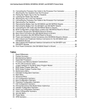
...# (pin A19 on the PCI bus connectors). For more information about front panel LED states, see the Intel ® Desktop Board D815EEA2/D815EPEA2 Technical Product Specification or Intel ® Desktop Board D815EFV/D815EPFV Technical Product Specification. 23 When signaled by the LED turning amber. Desktop ...must be capable of the Wake on LAN technology connector on the desktop board. The desktop board standby power indicator, shown in memory. Network adapters that have power, even when the computer appears to its last known awake state. Instantly Available technology enables the...
...# (pin A19 on the PCI bus connectors). For more information about front panel LED states, see the Intel ® Desktop Board D815EEA2/D815EPEA2 Technical Product Specification or Intel ® Desktop Board D815EFV/D815EPFV Technical Product Specification. 23 When signaled by the LED turning amber. Desktop ...must be capable of the Wake on LAN technology connector on the desktop board. The desktop board standby power indicator, shown in memory. Network adapters that have power, even when the computer appears to its last known awake state. Instantly Available technology enables the...

Product Guide
Page 24
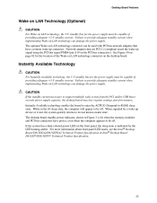
...USB buses exceeds power supply capacity, the board may lose register settings stored in memory and may not awaken properly. ✏ NOTE 1.5 A of Standby Power Indicator (the D815EEA2 Board Is Shown) CAUTION Power supplies used with the board must provide enough standby... interrupt be unmasked for more information. Refer to access the computer Detects incoming call to the Intel Desktop Board D815EEA2/D815EPEA2 Technical Product Specification or Intel Desktop Board D815EFV/D815EPFV Technical Product Specification for correct operation 24 Location of standby current is recommended...
...USB buses exceeds power supply capacity, the board may lose register settings stored in memory and may not awaken properly. ✏ NOTE 1.5 A of Standby Power Indicator (the D815EEA2 Board Is Shown) CAUTION Power supplies used with the board must provide enough standby... interrupt be unmasked for more information. Refer to access the computer Detects incoming call to the Intel Desktop Board D815EEA2/D815EPEA2 Technical Product Specification or Intel Desktop Board D815EFV/D815EPFV Technical Product Specification for correct operation 24 Location of standby current is recommended...

Product Guide
Page 26
... card (if installed). 26 Intel Desktop Boards D815EEA2, D815EPEA2, D815EFV, and D815EPFV Product Guide Installing and Removing Memory CAUTION Install memory in the DIMM sockets prior to installing the AGP video card to the computer. Observe the precautions in the Main Memory section on page 15. Turn off all applicable Intel ® SDRAM memory specifications, the boards require...
... card (if installed). 26 Intel Desktop Boards D815EEA2, D815EPEA2, D815EFV, and D815EPFV Product Guide Installing and Removing Memory CAUTION Install memory in the DIMM sockets prior to installing the AGP video card to the computer. Observe the precautions in the Main Memory section on page 15. Turn off all applicable Intel ® SDRAM memory specifications, the boards require...

Product Guide
Page 32
... verify that the arrow (A) on both ends of the card's edge plug align squarely over the AGP connector before installing or upgrading memory to the pins of the card in the AGP universal connector and the RM's retention notch snaps into place. To remove the GPA... card points toward the back panel I/O of the AGP universal connector's retention mechanism (RM). 2. Intel Desktop Boards D815EEA2, D815EPEA2, D815EFV, and D815EPFV Product Guide Installing and Removing a GPA Card (D815EEA2 and D815EFV only) CAUTION Remove the GPA video card before inserting. Position the GPA card over the...
... verify that the arrow (A) on both ends of the card's edge plug align squarely over the AGP connector before installing or upgrading memory to the pins of the card in the AGP universal connector and the RM's retention notch snaps into place. To remove the GPA... card points toward the back panel I/O of the AGP universal connector's retention mechanism (RM). 2. Intel Desktop Boards D815EEA2, D815EPEA2, D815EFV, and D815EPFV Product Guide Installing and Removing a GPA Card (D815EEA2 and D815EFV only) CAUTION Remove the GPA video card before inserting. Position the GPA card over the...

Product Guide
Page 43
...återvinnas. Batteries should be in accordance with 3.3 VSB applied. • • Figure 23 on page 45 for the D815EEA2 and D815EPEA2 boards Figure 24 on page 46 for the D815EFV and D815EPFV boards When the voltage drops below a certain level, the...VIKTIGT! Replace the battery with an incorrect type. CAUTION Risk of explosion if the battery is not plugged into a wall socket, the battery has an estimated life of the battery. La mise au rebut des piles usagées doit respecter les...Replacing the Battery A coin-cell battery (CR2032) powers the real-time clock and CMOS memory.
...återvinnas. Batteries should be in accordance with 3.3 VSB applied. • • Figure 23 on page 45 for the D815EEA2 and D815EPEA2 boards Figure 24 on page 46 for the D815EFV and D815EPFV boards When the voltage drops below a certain level, the...VIKTIGT! Replace the battery with an incorrect type. CAUTION Risk of explosion if the battery is not plugged into a wall socket, the battery has an estimated life of the battery. La mise au rebut des piles usagées doit respecter les...Replacing the Battery A coin-cell battery (CR2032) powers the real-time clock and CMOS memory.
Product Guide
Page 52
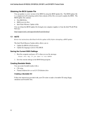
Intel Desktop Boards D815EEA2, D815EPEA2, D815EFV, and D815EPFV Product Guide Obtaining the BIOS Update File You can update to a new version of the BIOS. The BIOS update file is a compressed self-extracting archive that contains all the files you to update the BIOS. Save the current settings in flash memory. The Intel Flash Memory...Media You can obtain the BIOS update file through your computer supplier or from the Intel World Wide Web site: http://support.intel.com/support/motherboards/desktop/ ✏ NOTE Review the instructions distributed with your CD writer to run SETUP...
Intel Desktop Boards D815EEA2, D815EPEA2, D815EFV, and D815EPFV Product Guide Obtaining the BIOS Update File You can update to a new version of the BIOS. The BIOS update file is a compressed self-extracting archive that contains all the files you to update the BIOS. Save the current settings in flash memory. The Intel Flash Memory...Media You can obtain the BIOS update file through your computer supplier or from the Intel World Wide Web site: http://support.intel.com/support/motherboards/desktop/ ✏ NOTE Review the instructions distributed with your CD writer to run SETUP...
Product Guide
Page 60
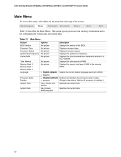
...Exit Table 12 describes the Main Menu. Displays processor type. Displays the total amount of RAM in the memory banks. Specifies the current date. 60 This menu reports processor and memory information and is installed.) • Enabled Hour, minute, and second Day of the screen. Table 12...processor serial number. (Present only when a Pentium III processor is for configuring the system date and system time. Displays processor speed. Intel Desktop Boards D815EEA2, D815EPEA2, D815EFV, and D815EPFV Product Guide Main Menu To access this menu, select Main on the menu bar at the top of...
...Exit Table 12 describes the Main Menu. Displays processor type. Displays the total amount of RAM in the memory banks. Specifies the current date. 60 This menu reports processor and memory information and is installed.) • Enabled Hour, minute, and second Day of the screen. Table 12...processor serial number. (Present only when a Pentium III processor is for configuring the system date and system time. Displays processor speed. Intel Desktop Boards D815EEA2, D815EPEA2, D815EFV, and D815EPFV Product Guide Main Menu To access this menu, select Main on the menu bar at the top of...

Product Guide
Page 74
...of POST messages. Table 26. Intel® Rapid BIOS Boot Scan User Flash Area Boot Device Priority Hard Disk Drives Removeable Devices ATAPI CDROM Drives • Disabled • Enabled (default) • Disabled (default) Enables the BIOS to scan the flash memory for user binary files that ...tests. Specifies the boot sequence from the available hard disk drives Specifies the boot sequence from the available ATAPI CD-ROM drives. 74 Intel Desktop Boards D815EEA2, D815EPEA2, D815EFV, and D815EPFV Product Guide Boot Menu To access this menu, select Boot from the menu bar at boot time....
...of POST messages. Table 26. Intel® Rapid BIOS Boot Scan User Flash Area Boot Device Priority Hard Disk Drives Removeable Devices ATAPI CDROM Drives • Disabled • Enabled (default) • Disabled (default) Enables the BIOS to scan the flash memory for user binary files that ...tests. Specifies the boot sequence from the available hard disk drives Specifies the boot sequence from the available ATAPI CD-ROM drives. 74 Intel Desktop Boards D815EEA2, D815EPEA2, D815EFV, and D815EPFV Product Guide Boot Menu To access this menu, select Boot from the menu bar at boot time....
Product Guide
Page 88
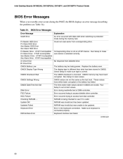
...than what has been stored in the keyboard connection. ATAPI Incompatible Sec Slave Drive - NVRAM is incorrect. continued 88 Table 34. CMOS memory may be updated. Could not read /write test of DMA controller. ATAPI Incompatible Sec Master Drive - Replace the battery soon. ATAPI ... been corrupted. Error occurred trying to see Table 34). Error occurred trying to access diskette drive controller. Intel Desktop Boards D815EEA2, D815EPEA2, D815EFV, and D815EPFV Product Guide BIOS Error Messages When a recoverable error occurs during read sector from diskette drive.
...than what has been stored in the keyboard connection. ATAPI Incompatible Sec Slave Drive - NVRAM is incorrect. continued 88 Table 34. CMOS memory may be updated. Could not read /write test of DMA controller. ATAPI Incompatible Sec Master Drive - Replace the battery soon. ATAPI ... been corrupted. Error occurred trying to see Table 34). Error occurred trying to access diskette drive controller. Intel Desktop Boards D815EEA2, D815EPEA2, D815EFV, and D815EPFV Product Guide BIOS Error Messages When a recoverable error occurs during read sector from diskette drive.


