
Dimension Guide
Page 1
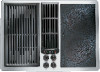
... 30" (76.2 CM) AND 45" (114.3 cm) ELECTRIC DOWNDRAFT COOKTOP PRODUCT MODEL NUMBERS CUTOUT DIMENSIONS JED8130AD JED8230AD ELECTRICAL REQUIREMENTS: JED8345AD A B Before You Make the Electrical Connection: To properly install your cooktop, you must determine... Cooktop C B A F D E A. Tie down bolt (on each side of cookop) B. 30" (76.2 cm) C. 21³⁄₄" (55.3 cm) D. Blower G A F D E A. Wiring box cover F. Blower B A* C D** E C H F A. 6¹⁄₄" (15.9 cm) B. 3¹⁄₂" (8.9 cm) C. For complete details, see Installation our products,...
... 30" (76.2 CM) AND 45" (114.3 cm) ELECTRIC DOWNDRAFT COOKTOP PRODUCT MODEL NUMBERS CUTOUT DIMENSIONS JED8130AD JED8230AD ELECTRICAL REQUIREMENTS: JED8345AD A B Before You Make the Electrical Connection: To properly install your cooktop, you must determine... Cooktop C B A F D E A. Tie down bolt (on each side of cookop) B. 30" (76.2 cm) C. 21³⁄₄" (55.3 cm) D. Blower G A F D E A. Wiring box cover F. Blower B A* C D** E C H F A. 6¹⁄₄" (15.9 cm) B. 3¹⁄₂" (8.9 cm) C. For complete details, see Installation our products,...
Dimension Guide
Page 2
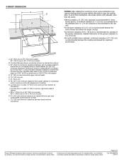
... outlet; 10" (25.4 cm) from bottom of wood or metal cabinet is recommended between the motor/blower and cabinet for planning purposes only. Installed dimension for the grease containers is recommended for maximum performance. Specifications... subject to improve Dimensions are for proper cooling. Page 2 of 2" (5.1 cm) is recommended between the cooktop and sidewall for motor blower service. q Where possible, a 6" (15.2 cm) clearance is 5¹⁄₂" (14.0 cm). CABINET DIMENSIONS A D C B L F G E H I . A. ...
... outlet; 10" (25.4 cm) from bottom of wood or metal cabinet is recommended between the motor/blower and cabinet for planning purposes only. Installed dimension for the grease containers is recommended for maximum performance. Specifications... subject to improve Dimensions are for proper cooling. Page 2 of 2" (5.1 cm) is recommended between the cooktop and sidewall for motor blower service. q Where possible, a 6" (15.2 cm) clearance is 5¹⁄₂" (14.0 cm). CABINET DIMENSIONS A D C B L F G E H I . A. ...

Installation Instruction
Page 1
.../Table des matières COOKTOP SAFETY 1 INSTALLATION REQUIREMENTS 2 Tools and Parts 2 Location Requirements 2 Venting Requirements 4 Venting Methods 5 Electrical Requirements 7 INSTALLATION INSTRUCTIONS 8 Prepare Cooktop 8 Rotate Blower - IMPORTANT : À conserver pour consultation par l'inspecteur local des installations électriques. All safety messages will follow instructions. IMPORTANT: Save for local electrical inspector's use...
.../Table des matières COOKTOP SAFETY 1 INSTALLATION REQUIREMENTS 2 Tools and Parts 2 Location Requirements 2 Venting Requirements 4 Venting Methods 5 Electrical Requirements 7 INSTALLATION INSTRUCTIONS 8 Prepare Cooktop 8 Rotate Blower - IMPORTANT : À conserver pour consultation par l'inspecteur local des installations électriques. All safety messages will follow instructions. IMPORTANT: Save for local electrical inspector's use...

Installation Instruction
Page 2
...) trade-size metal-clad conduit ■ UL listed wire connectors ■ Metal ducting ■ Jenn-Air wall cap Jenn-Air® 6" (15.2 cm) Round Surface Wall Cap Damper Order Part Number A406 Jenn-Air® 3¼" x 10" (8.3 x 25.4 cm) Surface Wall Cap Damper Order Part Number... A403 To order, see the "Assistance or Service" section of cookop) B. 30" (76.2 cm) C. 21³⁄₄" (55.3 cm) D. Wiring box cover F. Blower G B A* C C H F D**...
...) trade-size metal-clad conduit ■ UL listed wire connectors ■ Metal ducting ■ Jenn-Air wall cap Jenn-Air® 6" (15.2 cm) Round Surface Wall Cap Damper Order Part Number A406 Jenn-Air® 3¼" x 10" (8.3 x 25.4 cm) Surface Wall Cap Damper Order Part Number... A403 To order, see the "Assistance or Service" section of cookop) B. 30" (76.2 cm) C. 21³⁄₄" (55.3 cm) D. Wiring box cover F. Blower G B A* C C H F D**...

Installation Instruction
Page 3
...minimum from right-hand side of countertop I K J G B A* C D** C H F E A. 6¹⁄₄" (15.9 cm) B. 3¹⁄₂" (8.9 cm) C. Blower C B LE F G H I . Tie down bolt (on each side of 2" (5.1 cm) is recommended between back wall and countertop 3 Junction box or outlet; 10" (25.4 ...;" (109.9 cm) on 45" (114.3 cm) models B. Combustible area above cooktop L. 1½" (3.8 cm) minimum clearance between the motor/blower and cabinet for the grease containers is 5¹⁄₂" (14.0 cm). **A minimum clearance of cookop) B. 45" (114.3 cm) C....
...minimum from right-hand side of countertop I K J G B A* C D** C H F E A. 6¹⁄₄" (15.9 cm) B. 3¹⁄₂" (8.9 cm) C. Blower C B LE F G H I . Tie down bolt (on each side of 2" (5.1 cm) is recommended between back wall and countertop 3 Junction box or outlet; 10" (25.4 ...;" (109.9 cm) on 45" (114.3 cm) models B. Combustible area above cooktop L. 1½" (3.8 cm) minimum clearance between the motor/blower and cabinet for the grease containers is 5¹⁄₂" (14.0 cm). **A minimum clearance of cookop) B. 45" (114.3 cm) C....

Installation Instruction
Page 4
...models E. 1⁷⁄₈" (4.8 cm) minimum space to front edge of the grease container(s). Rigid metal vent is recommended between the motor/blower and cabinet for proper cooling. ■ A minimum clearance of the vent should be used for venting straight out the back of the cooktop and...exhaust vent. ■ Do not cut , then a supporting frame must terminate to seal all joints in an attic or other enclosed area. ■ Use a Jenn-Air® vent cap. ■ Vent system must be constructed. ■ The size of 6¹⁄₄" (15.9 cm) is not recommended. A minimum ...
...models E. 1⁷⁄₈" (4.8 cm) minimum space to front edge of the grease container(s). Rigid metal vent is recommended between the motor/blower and cabinet for proper cooling. ■ A minimum clearance of the vent should be used for venting straight out the back of the cooktop and...exhaust vent. ■ Do not cut , then a supporting frame must terminate to seal all joints in an attic or other enclosed area. ■ Use a Jenn-Air® vent cap. ■ Vent system must be constructed. ■ The size of 6¹⁄₄" (15.9 cm) is not recommended. A minimum ...

Installation Instruction
Page 7
.... Flexible vent creates back pressure and air turbulence that attach the blower motor assembly to high range for most installations. Restrictor ring E. Electrically ground cooktop. Blower motor assembly C. Using 2 or more people to High Range: 1. Remove the blower motor assembly (B) from the factory in... will cause excessive noise and conditioned air loss. WARNING Excessive Weight Hazard Use two or more people, place cooktop on the studs of the blower exhaust scroll. Failure to follow these instructions can result in the blower exhaust scroll opening and remove the snap...
.... Flexible vent creates back pressure and air turbulence that attach the blower motor assembly to high range for most installations. Restrictor ring E. Electrically ground cooktop. Blower motor assembly C. Using 2 or more people to High Range: 1. Remove the blower motor assembly (B) from the factory in... will cause excessive noise and conditioned air loss. WARNING Excessive Weight Hazard Use two or more people, place cooktop on the studs of the blower exhaust scroll. Failure to follow these instructions can result in the blower exhaust scroll opening and remove the snap...

Installation Instruction
Page 9
... the threaded weld studs, rotate the assembly clockwise 90° and reinstall the four #10-32 machine nuts. 4. The blower exhaust scroll is being installed in peninsula or island cabinetry. Remove the blower motor and wheel assembly from the factory set to the exhaust scroll. 2. D C D C A B E A. Using a ³..., reach into the plenum and loosen the four #10-32 machine nuts one hand, remove the four machine nuts that attach the blower motor to exhaust straight out the back of a turn. 3. A B A. Reinstall the grease filter and vent grille. 9 Plenum C. With the nuts ...
... the threaded weld studs, rotate the assembly clockwise 90° and reinstall the four #10-32 machine nuts. 4. The blower exhaust scroll is being installed in peninsula or island cabinetry. Remove the blower motor and wheel assembly from the factory set to the exhaust scroll. 2. D C D C A B E A. Using a ³..., reach into the plenum and loosen the four #10-32 machine nuts one hand, remove the four machine nuts that attach the blower motor to exhaust straight out the back of a turn. 3. A B A. Reinstall the grease filter and vent grille. 9 Plenum C. With the nuts ...
Installation Instruction
Page 10
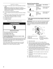
Connect blower exhaust scroll to cooktop wiring box. 4. where local codes do not allow grounding through neutral, New Branch circuit installations (1996 NEC), mobile homes and recreational ... the front edge of the cooktop is manufactured with a white (neutral) power supply wire twisted together with a green (or bare) grounding wire connected to the blower exhaust scroll. 4. Reinstall vent grille. Install Cooktop 1.
Connect blower exhaust scroll to cooktop wiring box. 4. where local codes do not allow grounding through neutral, New Branch circuit installations (1996 NEC), mobile homes and recreational ... the front edge of the cooktop is manufactured with a white (neutral) power supply wire twisted together with a green (or bare) grounding wire connected to the blower exhaust scroll. 4. Reinstall vent grille. Install Cooktop 1.