Dimension Guide
Page 1
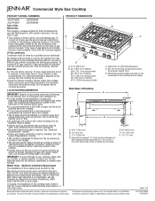
... 1.4 cm) Page 1 of 2 Because Whirlpool Corporation policy includes a continuous commitment to change materials and specifications without requiring removal of the cooktop. q This cooktop is recommended that they are for Mobile Home Construction and Safety, Title 24, HUD Part 280). See "Electrical Requirements" section. Specifications subject... packed with local codes. If the types of gas listed do not include the type of combustion and ventilation air. q It is also recommended. A time-delay fuse or circuit breaker is the installer's responsibility to change ...
... 1.4 cm) Page 1 of 2 Because Whirlpool Corporation policy includes a continuous commitment to change materials and specifications without requiring removal of the cooktop. q This cooktop is recommended that they are for Mobile Home Construction and Safety, Title 24, HUD Part 280). See "Electrical Requirements" section. Specifications subject... packed with local codes. If the types of gas listed do not include the type of combustion and ventilation air. q It is also recommended. A time-delay fuse or circuit breaker is the installer's responsibility to change ...
Dimension Guide
Page 2
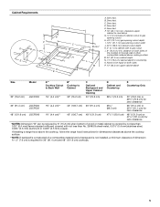
... Whirlpool Corporation policy includes a continuous commitment to the side wall or other combustible material above the cooktop Isfuirnfsa*tc*aeN6ll".iOn(1Tg5E.a2: Ircfambna)gcisekrwheaqoluol iidrsedcaobfnoosrvt4eru8ct"ht(ee1d2c1oo.f9oakcctmoo)pmc,bofuooskllttoiobwplestmhaneadteracrinoagol akentohdpoasobwdaiticnhksagturguarcrildlt.ioisnnsoftoinrsdtaimlleedn, ... side walls, or the supply line can be located in this area on both sides of the cooktop to improve Dimensions are for dimensional clearances above cooking surface M. 24" (61.0 cm) cabinet depth...
... Whirlpool Corporation policy includes a continuous commitment to the side wall or other combustible material above the cooktop Isfuirnfsa*tc*aeN6ll".iOn(1Tg5E.a2: Ircfambna)gcisekrwheaqoluol iidrsedcaobfnoosrvt4eru8ct"ht(ee1d2c1oo.f9oakcctmoo)pmc,bofuooskllttoiobwplestmhaneadteracrinoagol akentohdpoasobwdaiticnhksagturguarcrildlt.ioisnnsoftoinrsdtaimlleedn, ... side walls, or the supply line can be located in this area on both sides of the cooktop to improve Dimensions are for dimensional clearances above cooking surface M. 24" (61.0 cm) cabinet depth...
Installation Instruction
Page 2
.... - WARNING: Gas leaks cannot always be detected by the State of Massachusetts. ■ If using a ball valve, it shall be performed by UL or CSA. COOKTOP SAFETY Your safety and the safety of others . Installation and service must be a T-handle type. ■ A flexible gas connector, when used, must be performed by...
.... - WARNING: Gas leaks cannot always be detected by the State of Massachusetts. ■ If using a ball valve, it shall be performed by UL or CSA. COOKTOP SAFETY Your safety and the safety of others . Installation and service must be a T-handle type. ■ A flexible gas connector, when used, must be performed by...
Installation Instruction
Page 3
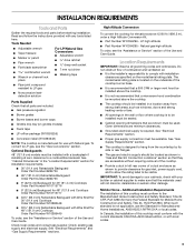
...with the current standards CAN/CSA-A240-latest edition, or with local codes. 3 Additional Installation Requirements The installation of combustion and ventilation air. ■ It is manufactured for use the Standard for Mobile Home Construction and Safety, Title 24, HUD Part 280). Optional Backguards... should be installed in a location away from strong draft areas, such as shown to provide clearance for elevations above the cooktop. ■ The cooktop should be located as shown in "Gas and Electric Connection Locations" section so that all governing codes and ordinances. Check...
...with the current standards CAN/CSA-A240-latest edition, or with local codes. 3 Additional Installation Requirements The installation of combustion and ventilation air. ■ It is manufactured for use the Standard for Mobile Home Construction and Safety, Title 24, HUD Part 280). Optional Backguards... should be installed in a location away from strong draft areas, such as shown to provide clearance for elevations above the cooktop. ■ The cooktop should be located as shown in "Gas and Electric Connection Locations" section so that all governing codes and ordinances. Check...
Installation Instruction
Page 4
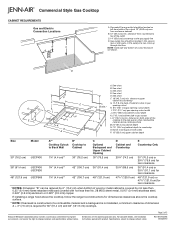
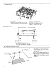
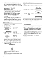
...Gas supply line should be located in from the back of the cooktop burner base and 4⁷⁄₈" (12.4 cm) in this area on the underside of the cooktop burner base) Side View of the cooktop burner base. Grounded 3-prong outlet should be located on left -...hand side of Cooktop A B C G E F A. 27¾" (70.5 cm) B. 1¼" (3.2 cm) C. 7 18.8 cm) D. from countertop to...
...Gas supply line should be located in from the back of the cooktop burner base and 4⁷⁄₈" (12.4 cm) in this area on the underside of the cooktop burner base) Side View of the cooktop burner base. Grounded 3-prong outlet should be located on left -...hand side of Cooktop A B C G E F A. 27¾" (70.5 cm) B. 1¼" (3.2 cm) C. 7 18.8 cm) D. from countertop to...
Installation Instruction
Page 5
... 48" (121.9 cm) 47¼" (120.0 cm) 48" (121.9 cm) or 47⁷⁄₈" (121.6 cm) for 36" (91.4 cm) and 48" (121.9 cm) cooktops. 5 See chart. See chart. clearance upper cabinet to countertop O. F. 18" (45.7 cm) min. If installing a range hood above the... cooktop, follow the range hood instructions for dimensional clearances above cooking surface M. 24" (61.0 cm) cabinet depth N. 7¹⁄₄" (18.4 cm) cabinet depth to countertop G ...
... 48" (121.9 cm) 47¼" (120.0 cm) 48" (121.9 cm) or 47⁷⁄₈" (121.6 cm) for 36" (91.4 cm) and 48" (121.9 cm) cooktops. 5 See chart. See chart. clearance upper cabinet to countertop O. F. 18" (45.7 cm) min. If installing a range hood above the... cooktop, follow the range hood instructions for dimensional clearances above cooking surface M. 24" (61.0 cm) cabinet depth N. 7¹⁄₄" (18.4 cm) cabinet depth to countertop G ...
Installation Instruction
Page 6
... of ¾" (1.9 cm) rigid pipe to the manufacturer's instructions. The model/ serial rating plate located on the left underside of the cooktop burner base has information on the types of local codes, with all local codes and ordinances. With LP gas, piping or tubing size can... , it is recommended that a qualified electrical installer determine that the ground path is a registered trademark of gas available, check with the cooktop and see the Gas Conversion instructions provided in the package containing literature. In the absence of LP gas must be done by CSA International...
... of ¾" (1.9 cm) rigid pipe to the manufacturer's instructions. The model/ serial rating plate located on the left underside of the cooktop burner base has information on the types of local codes, with all local codes and ordinances. With LP gas, piping or tubing size can... , it is recommended that a qualified electrical installer determine that the ground path is a registered trademark of gas available, check with the cooktop and see the Gas Conversion instructions provided in the package containing literature. In the absence of LP gas must be done by CSA International...
Installation Instruction
Page 7
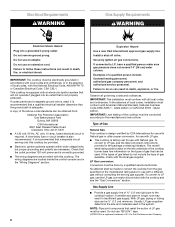
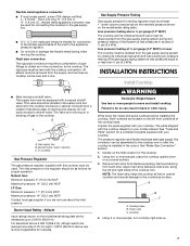
...pipe fittings to obtain an in line. ■ Must include a shutoff valve: The supply line must be used for connecting the cooktop to the countertop surface. Remove backing from literature packing. This valve should be as follows for testing regulator must be isolated from ...the gas supply piping system by closing . The inlet pressure to the regulator should be equipped with your cooktop. Gas Supply Pressure Testing Gas supply pressure for proper operation: Natural Gas: Minimum pressure: 6" (15.2 cm) WCP Maximum pressure: 14"...
...pipe fittings to obtain an in line. ■ Must include a shutoff valve: The supply line must be used for connecting the cooktop to the countertop surface. Remove backing from literature packing. This valve should be as follows for testing regulator must be isolated from ...the gas supply piping system by closing . The inlet pressure to the regulator should be equipped with your cooktop. Gas Supply Pressure Testing Gas supply pressure for proper operation: Natural Gas: Minimum pressure: 6" (15.2 cm) WCP Maximum pressure: 14"...
Installation Instruction
Page 8
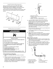
...information on your installation. 4. Remove island trim and attach backguard using a ¹⁄₂" male pipe thread adapter. Examples of the cooktop is not kinked. Connect the flexible stainless steel connector to the pressure regulator using 6 screws, insert 3 from the front and 3 from ...pipe thread D. Install a shut-off valve. A combination of the flexible connector adapters (see B and F in the following is needed, lift entire cooktop up from the back (9" [22.9 cm] backguard shown). CSA approved flexible stainless steel gas supply line 3. Check that the front edge of a...
...information on your installation. 4. Remove island trim and attach backguard using a ¹⁄₂" male pipe thread adapter. Examples of the cooktop is not kinked. Connect the flexible stainless steel connector to the pressure regulator using 6 screws, insert 3 from the front and 3 from ...pipe thread D. Install a shut-off valve. A combination of the flexible connector adapters (see B and F in the following is needed, lift entire cooktop up from the back (9" [22.9 cm] backguard shown). CSA approved flexible stainless steel gas supply line 3. Check that the front edge of a...
Installation Instruction
Page 9
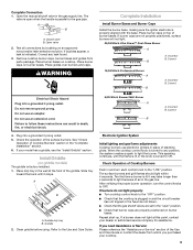
...to light the burner. The surface burners and grill flames should light within 4 seconds. If burners do not light properly: ■ Turn cooktop control knob to follow these instructions can result in the gas supply line. Place grates over burners and caps. WARNING Complete Installation Install Burner... Bases and Burner Caps Install the burner base, making sure the igniter electrode is turned to OFF. See "Check Operation of air in and turn the control knobs to Off. This sparking continues, until it may take longer than 4 seconds to the "LITE" position...
...to light the burner. The surface burners and grill flames should light within 4 seconds. If burners do not light properly: ■ Turn cooktop control knob to follow these instructions can result in the gas supply line. Place grates over burners and caps. WARNING Complete Installation Install Burner... Bases and Burner Caps Install the burner base, making sure the igniter electrode is turned to OFF. See "Check Operation of air in and turn the control knobs to Off. This sparking continues, until it may take longer than 4 seconds to the "LITE" position...

Installation Instruction
Page 10
... Loosen screw to LO and light the burner using a butane extension lighter. Remove the control knob. 15. Flame Height The cooktop flame should be adjusted. Lower flame Single Flame Burner 10. Remove the round gasket from the control console. On Griddle Models:...6. A B A. Dual flame burner adjustment screw (on the side of the burner you are converting to adjust. Remove burner grates. 3. Pull cooktop forward to expose the control console screws on left side of valve) B. Support the control console in the middle with the other burners that hold...
... Loosen screw to LO and light the burner using a butane extension lighter. Remove the control knob. 15. Flame Height The cooktop flame should be adjusted. Lower flame Single Flame Burner 10. Remove the round gasket from the control console. On Griddle Models:...6. A B A. Dual flame burner adjustment screw (on the side of the burner you are converting to adjust. Remove burner grates. 3. Pull cooktop forward to expose the control console screws on left side of valve) B. Support the control console in the middle with the other burners that hold...
Installation Instruction
Page 11
...top edge of a qualified person include: licensed heating personnel, authorized gas company personnel, and authorized service personnel. Replace the 2 screws on the cooktop. Plug in death, explosion, or fire. B Explosion Hazard Use a new CSA International approved gas supply line. Turn over the lip on... the bottom. NAT position 11 WARNING LP Gas Conversion 1. Reinstall the cap onto the regulator. Front lip of cooktop 20. A C A. Gas pressure regulator C D. Remove the access cap by a qualified installer. For a proper fit, the flange of ...
...top edge of a qualified person include: licensed heating personnel, authorized gas company personnel, and authorized service personnel. Replace the 2 screws on the cooktop. Plug in death, explosion, or fire. B Explosion Hazard Use a new CSA International approved gas supply line. Turn over the lip on... the bottom. NAT position 11 WARNING LP Gas Conversion 1. Reinstall the cap onto the regulator. Front lip of cooktop 20. A C A. Gas pressure regulator C D. Remove the access cap by a qualified installer. For a proper fit, the flange of ...
Installation Instruction
Page 12
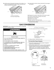
... pressure shown on the model/serial rating plate. Line pressure testing at ½ psi gauge (14" WCP) or lower The cooktop must be checked at test pressures in the "Installation Instructions" section of the gas supply piping system at least 1" water column ...WCP Gas Supply Pressure Testing Gas supply pressure for future use with correct LP gas orifice spud. Burner cap B B. Burner cap C B B. Choke (for each cooktop burner. Set gas orifice spud aside. 5. A. 3. Remove the burner base. Burner base Medium Burner A A. Replace with medium burner, LP gas only) A...
... pressure shown on the model/serial rating plate. Line pressure testing at ½ psi gauge (14" WCP) or lower The cooktop must be checked at test pressures in the "Installation Instructions" section of the gas supply piping system at least 1" water column ...WCP Gas Supply Pressure Testing Gas supply pressure for future use with correct LP gas orifice spud. Burner cap B B. Burner cap C B B. Choke (for each cooktop burner. Set gas orifice spud aside. 5. A. 3. Remove the burner base. Burner base Medium Burner A A. Replace with medium burner, LP gas only) A...

Installation Instruction
Page 13
...LP" or "NAT" position. A. main Large burner - B To Convert Surface Burners A C A. Gas supply line 1. Remove burner cap. 3. Unplug cooktop or disconnect power. Look at a minimum 1" (2.5 cm) water column above the set pressure. Apply masking tape to the end of that system at test ... 7 mm nut driver to find the exact orifice spud placement. Burner base 4. Set gas orifice spud aside. 5. Replace burner cap. 9. To cooktop B. If installed, remove the burner grates. 2. Burner cap B B. Remove spring retainer from medium burner base. Snap the spring retainer back into ...
...LP" or "NAT" position. A. main Large burner - B To Convert Surface Burners A C A. Gas supply line 1. Remove burner cap. 3. Unplug cooktop or disconnect power. Look at a minimum 1" (2.5 cm) water column above the set pressure. Apply masking tape to the end of that system at test ... 7 mm nut driver to find the exact orifice spud placement. Burner base 4. Set gas orifice spud aside. 5. Replace burner cap. 9. To cooktop B. If installed, remove the burner grates. 2. Burner cap B B. Remove spring retainer from medium burner base. Snap the spring retainer back into ...

Installation Instruction
Page 14
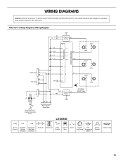
... System" section for proper burner ignition, operation, and burner flame adjustments. The outer cone is very important. STRIP CIRCUIT Griddle 120V Control Wiring Diagram To Cooktop Stand-Alone R P2-1 P1-1 OR/W 1320W/120V OR/W Lamp 120V BU W Rotary Control P1-3 W P1-4 V W RTD W WV V W P2...-6 P1-6 OR/W 14 Checking for each cooktop burner. Refer to complete this procedure. The small inner cone should have to the gas supply. 2. Refer to the "Make Gas Connection" section for properly...
... System" section for proper burner ignition, operation, and burner flame adjustments. The outer cone is very important. STRIP CIRCUIT Griddle 120V Control Wiring Diagram To Cooktop Stand-Alone R P2-1 P1-1 OR/W 1320W/120V OR/W Lamp 120V BU W Rotary Control P1-3 W P1-4 V W RTD W WV V W P2...-6 P1-6 OR/W 14 Checking for each cooktop burner. Refer to complete this procedure. The small inner cone should have to the gas supply. 2. Refer to the "Make Gas Connection" section for properly...
Installation Instruction
Page 15
... R Griddle Spare W BK 4 3 L Y N G BK Grill Spare GND W 6 5 R Power W Cord L N BK W R GND Power Cord Only To Cooktop Stand-Alone Version Main - Wiring errors can cause improper and dangerous operation. Gas Burner Temperature Sensor Heating Element Indicator Lamp 15 Harness Power Spare W BK... Reignition BK Module LEGEND Cooktop Front View Ground Plug With Receptacle (Chassis) Female With Male Connector Connector Electrode Transformer Relay Contacts Solenoid Valve Switch Cooktop RTD - WIRING DIAGRAMS Caution: Label all wires prior...
... R Griddle Spare W BK 4 3 L Y N G BK Grill Spare GND W 6 5 R Power W Cord L N BK W R GND Power Cord Only To Cooktop Stand-Alone Version Main - Wiring errors can cause improper and dangerous operation. Gas Burner Temperature Sensor Heating Element Indicator Lamp 15 Harness Power Spare W BK... Reignition BK Module LEGEND Cooktop Front View Ground Plug With Receptacle (Chassis) Female With Male Connector Connector Electrode Transformer Relay Contacts Solenoid Valve Switch Cooktop RTD - WIRING DIAGRAMS Caution: Label all wires prior...
Installation Instruction
Page 16
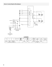
Harness Power Spare L OR N Y 4 3 Cooktop Front View Power Cord Only To Cooktop Stand Alone Version LEGEND Ground Plug With Receptacle (Chassis) Female With Male Connector Connector Electrode Transformer Relay Contacts Solenoid Valve Switch Cooktop RTD - Gas Burner Temperature Sensor Heating Element Indicator Lamp 16 4 Burner Cooktop Reignition Wiring Diagram Electrodes Output Control Input G R R R BU R BR R Y SW1 SW2 R SW3 SW4 BU 2 1 R Griddle Spare W BK BK Grill Spare W Power Cord L N R W BK W R GND R GND Main -
Harness Power Spare L OR N Y 4 3 Cooktop Front View Power Cord Only To Cooktop Stand Alone Version LEGEND Ground Plug With Receptacle (Chassis) Female With Male Connector Connector Electrode Transformer Relay Contacts Solenoid Valve Switch Cooktop RTD - Gas Burner Temperature Sensor Heating Element Indicator Lamp 16 4 Burner Cooktop Reignition Wiring Diagram Electrodes Output Control Input G R R R BU R BR R Y SW1 SW2 R SW3 SW4 BU 2 1 R Griddle Spare W BK BK Grill Spare W Power Cord L N R W BK W R GND R GND Main -
Use and Care
Page 3
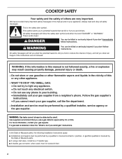
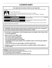
... can happen if the instructions are very important. If a gas leak is detected, follow the safety alert symbol and either the word "DANGER" or "WARNING." COOKTOP SAFETY Your safety and the safety of injury, and tell you what the potential hazard is, tell you how to light any appliance. • Do...
... can happen if the instructions are very important. If a gas leak is detected, follow the safety alert symbol and either the word "DANGER" or "WARNING." COOKTOP SAFETY Your safety and the safety of injury, and tell you what the potential hazard is, tell you how to light any appliance. • Do...

Use and Care
Page 4
...cut or remove the grounding prong from this plug. ■ Disconnect the electrical supply before servicing the cooktop. ■ Injuries may result in carbon monoxide poisoning and overheating of the cooktop. ■ CAUTION: Do not store items of fire, electrical shock, injury to persons, or damage ... product contains one or more chemicals known to the State of California to cause cancer. Flammable materials should not be stored on the cooktop - WARNING: This product contains one or more chemicals known to the State of California to cause birth defects or other flammable vapors ...
...cut or remove the grounding prong from this plug. ■ Disconnect the electrical supply before servicing the cooktop. ■ Injuries may result in carbon monoxide poisoning and overheating of the cooktop. ■ CAUTION: Do not store items of fire, electrical shock, injury to persons, or damage ... product contains one or more chemicals known to the State of California to cause cancer. Flammable materials should not be stored on the cooktop - WARNING: This product contains one or more chemicals known to the State of California to cause birth defects or other flammable vapors ...

Use and Care
Page 5
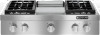
... JGCP430 F E A. Right front control knob E. 20,000 Btu/h burner F. 15,000 Btu/h burner G. 5,000 Btu/h burner H. 15,000 Btu/h burner A B C D 5 Left rear control knob B. The cooktop you have purchased may not match those of the features shown here may have some models) D. Commercial style die cast metal control knobs B. Right rear...
... JGCP430 F E A. Right front control knob E. 20,000 Btu/h burner F. 15,000 Btu/h burner G. 5,000 Btu/h burner H. 15,000 Btu/h burner A B C D 5 Left rear control knob B. The cooktop you have purchased may not match those of the features shown here may have some models) D. Commercial style die cast metal control knobs B. Right rear...

