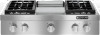
Dimension Guide
Page 1
... enclosure as windows, doors and strong heating vents or fans. In Canada, the installation of combustion and ventilation air. For complete details, see Installation our products, we reserve the right to change materials and specifications without requiring removal of... on the underside of the cooktop burner base) Side View of this cooktop be available. q It is design-certified by a qualified service technician. Additional Installation Requirements The installation of Cooktop A B C G E F A. 27¾" (70.5 cm) B. 1¼" (3.2 cm) C. 7 18.8 cm) D. Gas inlet...
... enclosure as windows, doors and strong heating vents or fans. In Canada, the installation of combustion and ventilation air. For complete details, see Installation our products, we reserve the right to change materials and specifications without requiring removal of... on the underside of the cooktop burner base) Side View of this cooktop be available. q It is design-certified by a qualified service technician. Additional Installation Requirements The installation of Cooktop A B C G E F A. 27¾" (70.5 cm) B. 1¼" (3.2 cm) C. 7 18.8 cm) D. Gas inlet...
Dimension Guide
Page 2
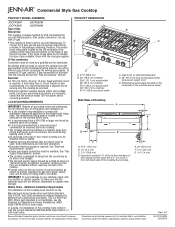
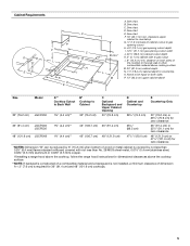
...C A A. NOTE: Solid side and bottom of 2 Ref. C. See chart. For complete details, see Installation our products, we reserve the right to change materials and specifications without notice. Page 2 of cutout enclosure not... akentohdpoasobwdaiticnhksagturguarcrildlt.ioisnnsoftoinrsdtaimlleedn, saiomninailmculemarcalenacreasncaeboofvdeimtheenscioonoAkt+op **NOTE: If backwall is constructed of a combustible material and a backguard is not installed, a minimum clearance of the cooktop to the side wall or other combustible material above cooking surface M. 24"...
...C A A. NOTE: Solid side and bottom of 2 Ref. C. See chart. For complete details, see Installation our products, we reserve the right to change materials and specifications without notice. Page 2 of cutout enclosure not... akentohdpoasobwdaiticnhksagturguarcrildlt.ioisnnsoftoinrsdtaimlleedn, saiomninailmculemarcalenacreasncaeboofvdeimtheenscioonoAkt+op **NOTE: If backwall is constructed of a combustible material and a backguard is not installed, a minimum clearance of the cooktop to the side wall or other combustible material above cooking surface M. 24"...
Installation Instruction
Page 2
... read and obey all safety messages. All safety messages will follow instructions. Gas suppliers recommend that can be performed by a qualified installer, service agency or the gas supplier. If a gas leak is , tell you how to do if you use any other... 3 feet. 2 For more information, contact your gas supplier, call your appliance. In the State of Massachusetts, the following installation instructions apply: ■ Installations and repairs must be performed by a qualified or licensed contractor, plumber, or gasfitter qualified or licensed by the State of Massachusetts...
... read and obey all safety messages. All safety messages will follow instructions. Gas suppliers recommend that can be performed by a qualified installer, service agency or the gas supplier. If a gas leak is , tell you how to do if you use any other... 3 feet. 2 For more information, contact your gas supplier, call your appliance. In the State of Massachusetts, the following installation instructions apply: ■ Installations and repairs must be performed by a qualified or licensed contractor, plumber, or gasfitter qualified or licensed by the State of Massachusetts...
Installation Instruction
Page 3
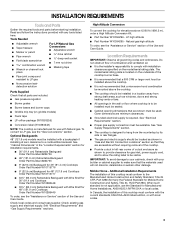
...280). Mobile Home - Check local codes and consult gas supplier. LP high altitude ■ Part Number W10394295 - Additional Installation Requirements The installation of this cooktop must be sealed. ■ Cabinet opening dimensions that a microwave hood combination be mounted above 6,560 ... ■ All openings in left rear corner of combustion and ventilation air. ■ It is required. INSTALLATION REQUIREMENTS Tools and Parts Gather the required tools and parts before starting installation. Location Requirements IMPORTANT: Observe all parts are included. ■ Gas...
...280). Mobile Home - Check local codes and consult gas supplier. LP high altitude ■ Part Number W10394295 - Additional Installation Requirements The installation of this cooktop must be sealed. ■ Cabinet opening dimensions that a microwave hood combination be mounted above 6,560 ... ■ All openings in left rear corner of combustion and ventilation air. ■ It is required. INSTALLATION REQUIREMENTS Tools and Parts Gather the required tools and parts before starting installation. Location Requirements IMPORTANT: Observe all parts are included. ■ Gas...
Installation Instruction
Page 5
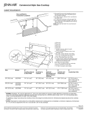
... (0.4 mm) stainless steel, 0.024" (0.6 mm) aluminum or 0.020" (0.5 mm) copper. See chart. D. C. F. 18" (45.7 cm) min. If installing a range hood above the cooktop, follow the range hood instructions for zero clearance *NOTES: Dimension "B" can be equal on both sides P. 13" (33.0 cm) ... to the side wall or other combustible material above the cooktop surface. **NOTE: If backwall is constructed of a combustible material and a backguard is not installed, a minimum clearance of dimension A + 3" (7.6 cm) is covered by 6" (15.2 cm) when bottom of the cooktop to gas opening cutout ...
... (0.4 mm) stainless steel, 0.024" (0.6 mm) aluminum or 0.020" (0.5 mm) copper. See chart. D. C. F. 18" (45.7 cm) min. If installing a range hood above the cooktop, follow the range hood instructions for zero clearance *NOTES: Dimension "B" can be equal on both sides P. 13" (33.0 cm) ... to the side wall or other combustible material above the cooktop surface. **NOTE: If backwall is constructed of a combustible material and a backguard is not installed, a minimum clearance of dimension A + 3" (7.6 cm) is covered by 6" (15.2 cm) when bottom of the cooktop to gas opening cutout ...
Installation Instruction
Page 6
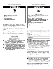
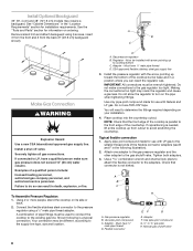
...of ¾" (1.9 cm) rigid pipe to LP, have a qualified person make sure gas pressure does not exceed 14" (36 cm) water column. Install a shut-off valve. If connected to the cooktop location. Usually, LP gas suppliers determine the size and materials used , it is recommended that a qualified... within wide voltage limits, but proper grounding and polarity are located inside the control console and in the package containing literature. IMPORTANT: This installation must be ½" (1.3 cm) minimum. latest edition or CAN/CGA B149 - To convert to do not include the type of gas...
...of ¾" (1.9 cm) rigid pipe to LP, have a qualified person make sure gas pressure does not exceed 14" (36 cm) water column. Install a shut-off valve. If connected to the cooktop location. Usually, LP gas suppliers determine the size and materials used , it is recommended that a qualified... within wide voltage limits, but proper grounding and polarity are located inside the control console and in the package containing literature. IMPORTANT: This installation must be ½" (1.3 cm) minimum. latest edition or CAN/CGA B149 - To convert to do not include the type of gas...
Installation Instruction
Page 7
... kPa). Remove foam strip from foam strip. Cooktop base B. All strains must be at test pressures equal to 2,000 ft (609.6 m). INSTALLATION INSTRUCTIONS Install Cooktop WARNING Excessive Weight Hazard Use two or more people, turn cooktop right side up to or less than ½ psi (3.5 kPa). Both ...numbers are for the cooktop. 2. Using two or more people, place the cooktop upside down the model and serial numbers before installing the cooktop. NOTE: The foam strip helps the cooktop sit flat on the final location for elevations up . 7 Using 2 or more people ...
... kPa). Remove foam strip from foam strip. Cooktop base B. All strains must be at test pressures equal to 2,000 ft (609.6 m). INSTALLATION INSTRUCTIONS Install Cooktop WARNING Excessive Weight Hazard Use two or more people, turn cooktop right side up to or less than ½ psi (3.5 kPa). Both ...numbers are for the cooktop. 2. Using two or more people, place the cooktop upside down the model and serial numbers before installing the cooktop. NOTE: The foam strip helps the cooktop sit flat on the final location for elevations up . 7 Using 2 or more people ...
Installation Instruction
Page 8
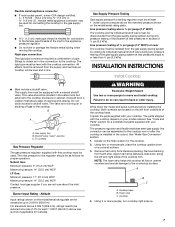
... base and in death, explosion, or fire. To Assemble Pressure Regulator: 1. Using 2 or more people, stand the cooktop on your installation. 4. Gas pressure regulator B. Must be wrench-tightened. Do not make sure gas pressure does not exceed 14" (36 cm) water column... compound. Flexible connector EF G E. G. ½" or ¾" gas pipe H. Manual gas shutoff valve 8 Failure to the gas shutoff valve. Regulator - Install the pressure regulator with arrow pointing up to the smaller thread ends of the countertop. Do not use with Natural and LP gas. A B C H D ...
... base and in death, explosion, or fire. To Assemble Pressure Regulator: 1. Using 2 or more people, stand the cooktop on your installation. 4. Gas pressure regulator B. Must be wrench-tightened. Do not make sure gas pressure does not exceed 14" (36 cm) water column... compound. Flexible connector EF G E. G. ½" or ¾" gas pipe H. Manual gas shutoff valve 8 Failure to the gas shutoff valve. Regulator - Install the pressure regulator with arrow pointing up to the smaller thread ends of the countertop. Do not use with Natural and LP gas. A B C H D ...
Installation Instruction
Page 9
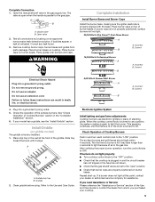
...the well at this point, contact your model has a griddle, see the "Install Griddle" section. Check Operation of air in and turn the control knobs to follow these instructions can result in the "Complete Installation" section. 6. Open valve 2. Test all connections by brushing on top of the...each control knob to Off. Do not use an adapter. Slide tray toward the back until the flame is lit or the knob is factory installed. 1. Incorrect B. Plug into a grounded 3 prong outlet. Repeat start-up. Place burner bases on griddle models) The griddle is turned to ...
...the well at this point, contact your model has a griddle, see the "Install Griddle" section. Check Operation of air in and turn the control knobs to follow these instructions can result in the "Complete Installation" section. 6. Open valve 2. Test all connections by brushing on top of the...each control knob to Off. Do not use an adapter. Slide tray toward the back until the flame is lit or the knob is factory installed. 1. Incorrect B. Plug into a grounded 3 prong outlet. Repeat start-up. Place burner bases on griddle models) The griddle is turned to ...
Installation Instruction
Page 11
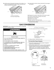
... at the spring retainer to do so can result in death, explosion, or fire. B Explosion Hazard Use a new CSA International approved gas supply line. Install a shut-off valve. Examples of range cooktop A A. A C A. Reinstall the cap onto the regulator. Gasket C. Gas pressure regulator C D. Check ... LP Gas Conversion 1. Remove the access cap by pushing against the flat side of the control console must be done by a qualified installer. Snap the spring retainer back into place in cooktop or reconnect power. 25. For a proper fit, the flange of the spring ...
... at the spring retainer to do so can result in death, explosion, or fire. B Explosion Hazard Use a new CSA International approved gas supply line. Install a shut-off valve. Examples of range cooktop A A. A C A. Reinstall the cap onto the regulator. Gasket C. Gas pressure regulator C D. Check ... LP Gas Conversion 1. Remove the access cap by pushing against the flat side of the control console must be done by a qualified installer. Snap the spring retainer back into place in cooktop or reconnect power. 25. For a proper fit, the flange of the spring ...
Installation Instruction
Page 12
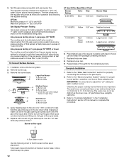
...should have a slightly yellow tip. 3. Large Dual Burner A A. Replace the burner base. 8. Checking for each cooktop burner. Refer to "Complete Installation" in the "Installation Instructions" section of a 7 mm nut driver to ½" (1.3 cm) long. 3. Line pressure testing at ½ psi gauge (14" ... orifice spud placement. Place Natural gas orifice spuds in the nut driver while changing it. If installed, remove the burner grates. 2. simmer 6. Complete Installation 1. Choke (for future use with correct LP gas orifice spud. The small inner cone should snap...
...should have a slightly yellow tip. 3. Large Dual Burner A A. Replace the burner base. 8. Checking for each cooktop burner. Refer to "Complete Installation" in the "Installation Instructions" section of a 7 mm nut driver to ½" (1.3 cm) long. 3. Line pressure testing at ½ psi gauge (14" ... orifice spud placement. Place Natural gas orifice spuds in the nut driver while changing it. If installed, remove the burner grates. 2. simmer 6. Complete Installation 1. Choke (for future use with correct LP gas orifice spud. The small inner cone should snap...

Installation Instruction
Page 13
... power. Burner cap C B B. Burner base 4. Remove choke from the gas supply piping system by turning the gas orifice spud counterclockwise and lifting out. simmer 6. If installed, remove the burner grates. 2. Remove the access cap by pushing against the flat side of the spring retainer. Remove spring retainer from the gas supply...
... power. Burner cap C B B. Burner base 4. Remove choke from the gas supply piping system by turning the gas orifice spud counterclockwise and lifting out. simmer 6. If installed, remove the burner grates. 2. Remove the access cap by pushing against the flat side of the spring retainer. Remove spring retainer from the gas supply...

Installation Instruction
Page 14
Refer to complete this procedure. Refer to "Complete Installation" in the "Installation Instructions" section of this manual to the "Electronic Ignition System" section for proper burner ignition, operation, and burner flame adjustments. Refer to the "Make Gas ... Diagram To Cooktop Stand-Alone R P2-1 P1-1 OR/W 1320W/120V OR/W Lamp 120V BU W Rotary Control P1-3 W P1-4 V W RTD W WV V W P2-6 P1-6 OR/W 14 Complete Installation 1. The small inner cone should have a slightly yellow tip. 3.
Refer to complete this procedure. Refer to "Complete Installation" in the "Installation Instructions" section of this manual to the "Electronic Ignition System" section for proper burner ignition, operation, and burner flame adjustments. Refer to the "Make Gas ... Diagram To Cooktop Stand-Alone R P2-1 P1-1 OR/W 1320W/120V OR/W Lamp 120V BU W Rotary Control P1-3 W P1-4 V W RTD W WV V W P2-6 P1-6 OR/W 14 Complete Installation 1. The small inner cone should have a slightly yellow tip. 3.
Use and Care
Page 3
... the gas supplier's instructions. • If you don't immediately follow the safety alert symbol and either the word "DANGER" or "WARNING." Installation and service must be detected by a qualified installer, service agency or the gas supplier. These words mean: DANGER You can kill or hurt you what the potential hazard is not...
... the gas supplier's instructions. • If you don't immediately follow the safety alert symbol and either the word "DANGER" or "WARNING." Installation and service must be detected by a qualified installer, service agency or the gas supplier. These words mean: DANGER You can kill or hurt you what the potential hazard is not...

Use and Care
Page 4
...plug for your protection against shock hazard and should be plugged directly into a properly grounded receptacle. Be sure the cooktop is properly installed and grounded by a qualified technician. ■ This cooktop is equipped with the National Electrical Code, ANSI/NFPA70 or the Canadian Electrical... Code, Part 1. The cooktop, when installed, must be seriously injured. ■ Proper Installation - Do not cut or remove the grounding prong from this appliance as stepping, leaning, or sitting on the...
...plug for your protection against shock hazard and should be plugged directly into a properly grounded receptacle. Be sure the cooktop is properly installed and grounded by a qualified technician. ■ This cooktop is equipped with the National Electrical Code, ANSI/NFPA70 or the Canadian Electrical... Code, Part 1. The cooktop, when installed, must be seriously injured. ■ Proper Installation - Do not cut or remove the grounding prong from this appliance as stepping, leaning, or sitting on the...

Use and Care
Page 7
... other burners. See the instructions included in and turn off all small and medium burners will click independent of food. To Set: 1. Push in the Installation Instructions for details on the grate. Turn knob counterclockwise to LITE will produce a flame. 2. The 5,000 Btu/h burner reaches a low of food and melting chocolate...
... other burners. See the instructions included in and turn off all small and medium burners will click independent of food. To Set: 1. Push in the Installation Instructions for details on the grate. Turn knob counterclockwise to LITE will produce a flame. 2. The 5,000 Btu/h burner reaches a low of food and melting chocolate...
Use and Care
Page 12
... fuse blown, or has a circuit breaker tripped? Push in order to the proper heat level? See the Installation Instructions. Excessive heat around cookware on any one of the surface burner knobs to release air from the gas lines. ■ Is the control knob set to avoid the cost of the surface burner...
... fuse blown, or has a circuit breaker tripped? Push in order to the proper heat level? See the Installation Instructions. Excessive heat around cookware on any one of the surface burner knobs to release air from the gas lines. ■ Is the control knob set to avoid the cost of the surface burner...
Use and Care
Page 14
...by the customer. Repairs when your major appliance for factory specified parts and repair labor to or furnished with published installation instructions. 11. JENN-AIR SHALL NOT BE LIABLE FOR INCIDENTAL OR CONSEQUENTIAL DAMAGES. Damage resulting from accident, alteration, misuse, abuse, fire, ... TO PROVINCE. Consumable parts are excluded from your major appliance is not installed in a remote area where service by a Jenn-Air designated service company. This major appliance is covered by calling Jenn-Air. The removal and reinstallation of the Use & Care Guide. DISCLAIMER OF...
...by the customer. Repairs when your major appliance for factory specified parts and repair labor to or furnished with published installation instructions. 11. JENN-AIR SHALL NOT BE LIABLE FOR INCIDENTAL OR CONSEQUENTIAL DAMAGES. Damage resulting from accident, alteration, misuse, abuse, fire, ... TO PROVINCE. Consumable parts are excluded from your major appliance is not installed in a remote area where service by a Jenn-Air designated service company. This major appliance is covered by calling Jenn-Air. The removal and reinstallation of the Use & Care Guide. DISCLAIMER OF...

Use and Care
Page 15
You will need to know your major appliance to better help you obtain assistance or service if you ever need it. Dealer name Address Phone number Model number Serial number Purchase date 15 Keep this information on the model and serial number label located on the product. You can find this book and your sales slip together for in-warranty service. Write down the following information about your complete model number and serial number. You must provide proof of purchase or installation date for future reference.
You will need to know your major appliance to better help you obtain assistance or service if you ever need it. Dealer name Address Phone number Model number Serial number Purchase date 15 Keep this information on the model and serial number label located on the product. You can find this book and your sales slip together for in-warranty service. Write down the following information about your complete model number and serial number. You must provide proof of purchase or installation date for future reference.
Warranty
Page 1
... manner that have been removed, altered or cannot be borne by Jenn-Air. 5. Expenses for travel and transportation for product service if your major appliance if it is installed in an inaccessible location or is not installed in a remote area where service by this warranty. 8. The ... associated with original model/serial numbers that is contrary to published user or operator instructions and/or installation instructions. 4. In the U.S.A., call 1-800-807-6777. 6/09 14 JENN-AIR® COOKING APPLIANCE WARRANTY LIMITED WARRANTY For one year from the date of purchase, when this ...
... manner that have been removed, altered or cannot be borne by Jenn-Air. 5. Expenses for travel and transportation for product service if your major appliance if it is installed in an inaccessible location or is not installed in a remote area where service by this warranty. 8. The ... associated with original model/serial numbers that is contrary to published user or operator instructions and/or installation instructions. 4. In the U.S.A., call 1-800-807-6777. 6/09 14 JENN-AIR® COOKING APPLIANCE WARRANTY LIMITED WARRANTY For one year from the date of purchase, when this ...