
FS-C5016N Operation Guide
Page 179
... Printer As discussed earlier, the following example explains the procedure to clean the main charger unit for each time the toner container and waste toner box are replaced: • Main charger wire • Main charger grid • Registration roller In addition to this, it is comprised of the toner container that corresponds to color...
... Printer As discussed earlier, the following example explains the procedure to clean the main charger unit for each time the toner container and waste toner box are replaced: • Main charger wire • Main charger grid • Registration roller In addition to this, it is comprised of the toner container that corresponds to color...

FS-C5016N Quick Reference Guide
Page 37
... and the grid - which should be cleaned periodically as explained below. 35 Cleaning the Printer The following parts must be cleaned each time the toner container is replaced: • Main charger wire • Main charger grid • Registration roller In addition to be separately as they get contaminated with dioxide after long usage...
... and the grid - which should be cleaned periodically as explained below. 35 Cleaning the Printer The following parts must be cleaned each time the toner container is replaced: • Main charger wire • Main charger grid • Registration roller In addition to be separately as they get contaminated with dioxide after long usage...

Service Manual
Page 6
...risk of damage. Check that the fixing unit thermistor, heat and press rollers are clean. Keep away from the wall outlet before starting machine disassembly • Always follow the procedures for routine replacement They are safely secured so they are charged to high potentials and ...or gap for installation of a part, always use the thermostat or thermal fuse specified in the service manual and other related brochure when replacing them can be caught in machines using lasers. Dirt on a powered machine. Precautions for Maintenance WARNING • Always remove the power ...
...risk of damage. Check that the fixing unit thermistor, heat and press rollers are clean. Keep away from the wall outlet before starting machine disassembly • Always follow the procedures for routine replacement They are safely secured so they are charged to high potentials and ...or gap for installation of a part, always use the thermostat or thermal fuse specified in the service manual and other related brochure when replacing them can be caught in machines using lasers. Dirt on a powered machine. Precautions for Maintenance WARNING • Always remove the power ...
Service Manual
Page 42
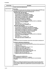
... 1-4-12 Replace the four developer units (See page 1-6-11). 5. Replace the fuser unit (See page 1-6-18). 6. Replace the retard roller (See page 1-6-7). 11. is reset immediately. This may be used to the new drum unit (See page 1-6-13). 3. Remove the LED print head... key twice. Replace the paper feed unit (See page 1-6-5). 7. Replace the MP tray feed roller (See page 1-6-10). Procedure for replacing the maintenance kit 1. Start Enter the service mode [>>Maintenance]. Press the ENTER key, ">>Maintenance ?" Install the four new drum units. 4. FS-C5016N Service items >>...
... 1-4-12 Replace the four developer units (See page 1-6-11). 5. Replace the fuser unit (See page 1-6-18). 6. Replace the retard roller (See page 1-6-7). 11. is reset immediately. This may be used to the new drum unit (See page 1-6-13). 3. Remove the LED print head... key twice. Replace the paper feed unit (See page 1-6-5). 7. Replace the MP tray feed roller (See page 1-6-10). Procedure for replacing the maintenance kit 1. Start Enter the service mode [>>Maintenance]. Press the ENTER key, ">>Maintenance ?" Install the four new drum units. 4. FS-C5016N Service items >>...

Service Manual
Page 53
... harness of the fuser thermistor 1, check the connection YC694 connector of mistor 1,if there is trouble, remedy or replace. Fuser abnormal high temperature error (heat roller) • Abnormal high fuser temperature of fuser thermistor 1. See page 1-6-25. Check the installation condition of fuser...supply PWB. See page 1-6-25. See page 1-6-18. Defective fuser heater lamp 1. FS-C5016N Code 6000 6020 Contents Causes Remarks Check procedures/corrective measures Fuser temperature time-out error (heat roller) • Doing the control which turns on the fuser heater lamp 1 which ...
... harness of the fuser thermistor 1, check the connection YC694 connector of mistor 1,if there is trouble, remedy or replace. Fuser abnormal high temperature error (heat roller) • Abnormal high fuser temperature of fuser thermistor 1. See page 1-6-25. Check the installation condition of fuser...supply PWB. See page 1-6-25. See page 1-6-18. Defective fuser heater lamp 1. FS-C5016N Code 6000 6020 Contents Causes Remarks Check procedures/corrective measures Fuser temperature time-out error (heat roller) • Doing the control which turns on the fuser heater lamp 1 which ...

Service Manual
Page 54
... thermistor 1 which detects the fuser temperature of the heat roller. replace. FS-C5016N Code 6030 Contents Causes Remarks Check procedures/corrective measures Fuser thermistor 1 broken error (heat roller) • It was judged it is trouble, remedy or replace. Defective harness of the fuser PWB (KP-970) between... fuser PWB (KP970) and fuser connector or poor contact of the connector terminals. Replace the engine controller PWB (KP1054)....
... thermistor 1 which detects the fuser temperature of the heat roller. replace. FS-C5016N Code 6030 Contents Causes Remarks Check procedures/corrective measures Fuser thermistor 1 broken error (heat roller) • It was judged it is trouble, remedy or replace. Defective harness of the fuser PWB (KP-970) between... fuser PWB (KP970) and fuser connector or poor contact of the connector terminals. Replace the engine controller PWB (KP1054)....

Service Manual
Page 55
... thermistor 2, or poor contact of mistor 2, if there is trouble, remedy or replace. See page 1-6-18. See page 1-6-25. Defective power supply PWB. FS-C5016N Code 6100 6120 Contents Causes Remarks Check procedures/corrective measures Fuser temperature time-out error (press roller) • Doing the control which turns on the fuser heater lamp 2 which...
... thermistor 2, or poor contact of mistor 2, if there is trouble, remedy or replace. See page 1-6-18. See page 1-6-25. Defective power supply PWB. FS-C5016N Code 6100 6120 Contents Causes Remarks Check procedures/corrective measures Fuser temperature time-out error (press roller) • Doing the control which turns on the fuser heater lamp 2 which...

Service Manual
Page 56
...) between fuser thermistor 2 or poor contact of toner replenishment drive system. See page 1-6-25. FS-C5016N Code 6130 6400 7001 Contents Causes Remarks Check procedures/corrective measures Fuser thermistor 2 broken error (press roller) • It was not detected. Replace the fuser PWB (KP-970). Defective installa- Defective engine controller PWB (KP-1054). See page...
...) between fuser thermistor 2 or poor contact of toner replenishment drive system. See page 1-6-25. FS-C5016N Code 6130 6400 7001 Contents Causes Remarks Check procedures/corrective measures Fuser thermistor 2 broken error (press roller) • It was not detected. Replace the fuser PWB (KP-970). Defective installa- Defective engine controller PWB (KP-1054). See page...

Service Manual
Page 67
... secondary transfer roller. 2. Clean the heat roller and press roller. FS-C5016N (3) A specific color is properly seated. Disconnected main charger wire. Check procedures/corrective measures Clean the secondary transfer roller. Defective main charger unit which corresponds to the color causing the ... roller and press roller. Clean the paper conveying path of the paper feed unit. 3. Causes 1. Causes 1. Disconnected main charger wire. sponds to the color causing the prob- Dirty secondary transfer roller. 2. Defective main charger unit which corre- Replace ...
... secondary transfer roller. 2. Clean the heat roller and press roller. FS-C5016N (3) A specific color is properly seated. Disconnected main charger wire. Check procedures/corrective measures Clean the secondary transfer roller. Defective main charger unit which corresponds to the color causing the ... roller and press roller. Clean the paper conveying path of the paper feed unit. 3. Causes 1. Causes 1. Disconnected main charger wire. sponds to the color causing the prob- Dirty secondary transfer roller. 2. Defective main charger unit which corre- Replace ...

Service Manual
Page 70
FS-C5016N (9) Streaks are printed. Poor contact of developing bias terminal of main charger unit. 2. Poor contact of output terminal of developer. Poor contact of grounding terminal of main charger unit. 2. Check procedures/corrective measures Insert the main charger properly. Dirty or flawed drum. 2. Flawed developing sleeve roller. Replace... the developer. Perform the heat roller and press roller cleaning. Causes 1. Replace the main controller PWB (KP-957). Poor contact of ...
FS-C5016N (9) Streaks are printed. Poor contact of developing bias terminal of main charger unit. 2. Poor contact of output terminal of developer. Poor contact of grounding terminal of main charger unit. 2. Check procedures/corrective measures Insert the main charger properly. Dirty or flawed drum. 2. Flawed developing sleeve roller. Replace... the developer. Perform the heat roller and press roller cleaning. Causes 1. Replace the main controller PWB (KP-957). Poor contact of ...

Service Manual
Page 72
... of paper. 2. Replace the heat roller or press roller. See page 1-6-18. (16) )Colors are printed offset to user's manual). Flawed heat roller or press roller. Check the fuser pressure springs. position. 1-5-28 Flawed heat roller or press roller. Defective pressure for the heat roller and press roller. 3. Causes Check procedures/corrective measures 1. Wrong types of paper. 2. FS-C5016N (15) Fusing is...
... of paper. 2. Replace the heat roller or press roller. See page 1-6-18. (16) )Colors are printed offset to user's manual). Flawed heat roller or press roller. Check the fuser pressure springs. position. 1-5-28 Flawed heat roller or press roller. Defective pressure for the heat roller and press roller. 3. Causes Check procedures/corrective measures 1. Wrong types of paper. 2. FS-C5016N (15) Fusing is...

Service Manual
Page 78
.... Check or replace the feed roller and then refit all the removed parts. Unlatch the latches and then remove paper feed roller unit. While pushing the lock release buttons and then detach the joint. 4. Latches Lock release button Joint 5. Unlatch the three latches and then remove the feed bracket cover. 6. FS-C5016N (2) Detaching and...
.... Check or replace the feed roller and then refit all the removed parts. Unlatch the latches and then remove paper feed roller unit. While pushing the lock release buttons and then detach the joint. 4. Latches Lock release button Joint 5. Unlatch the three latches and then remove the feed bracket cover. 6. FS-C5016N (2) Detaching and...

Service Manual
Page 79
Unlatch the two latches and then remove the retard roller holder. 3. Remove the paper cassette. 2. Remove the retard roller from retard roller holder. 4. (3) Detaching and refitting the retard roller Procedure 1. Check or replace the retard roller and then refit all the removed parts. Retard roller holder Retard roller FS-C5016N Paper cassette Latches Figure 1-6-10 1-6-7
Unlatch the two latches and then remove the retard roller holder. 3. Remove the paper cassette. 2. Remove the retard roller from retard roller holder. 4. (3) Detaching and refitting the retard roller Procedure 1. Check or replace the retard roller and then refit all the removed parts. Retard roller holder Retard roller FS-C5016N Paper cassette Latches Figure 1-6-10 1-6-7

Service Manual
Page 80
Check or replace the secondary transfer roller and then refit all the removed parts. Remove the transfer roller gear. 5. Remove the paper feed unit (see page 1-65). 2. Remove the secondary transfer roller. 4. Removing the hook by sliding and then remove the paper chute. 3. Paper chute Hook Hook Secondary transfer roller Transfer roller gear Hook Paper feed unit Figure 1-6-11 1-6-8 FS-C5016N (4) Detaching and refitting the secondary transfer roller Procedure 1.
Check or replace the secondary transfer roller and then refit all the removed parts. Remove the transfer roller gear. 5. Remove the paper feed unit (see page 1-65). 2. Remove the secondary transfer roller. 4. Removing the hook by sliding and then remove the paper chute. 3. Paper chute Hook Hook Secondary transfer roller Transfer roller gear Hook Paper feed unit Figure 1-6-11 1-6-8 FS-C5016N (4) Detaching and refitting the secondary transfer roller Procedure 1.

Service Manual
Page 82
Check or replace the MP tray feed roller and then refit all the removed parts. Remove the MP tray feed unit (see previous page). 2. Pull up the MP tray holder and then sliding do. 3. MP tray feed roller MP tray holder MP tray feed unit Figure 1-6-13 1-6-10 Remove the MP tray feed roller. 4. FS-C5016N (2) Detaching and refitting the MP tray feed roller Procedure 1.
Check or replace the MP tray feed roller and then refit all the removed parts. Remove the MP tray feed unit (see previous page). 2. Pull up the MP tray holder and then sliding do. 3. MP tray feed roller MP tray holder MP tray feed unit Figure 1-6-13 1-6-10 Remove the MP tray feed roller. 4. FS-C5016N (2) Detaching and refitting the MP tray feed roller Procedure 1.

Service Manual
Page 95
Check or replace the fuser thermistor 1 and 2, fuser thermostat 1 and 2, fuser heater lamp 1 and 2, heat roller and, press roller then refit all the removed parts. Remove the right stay, left stay and press roller. 26. Right stay Press roller Left stay FS-C5016N C-ring Bush Bearing Bearing Bush C-ring Figure 1-6-31 1-6-23 24. Remove the two bushes and two bearings. 25.
Check or replace the fuser thermistor 1 and 2, fuser thermostat 1 and 2, fuser heater lamp 1 and 2, heat roller and, press roller then refit all the removed parts. Remove the right stay, left stay and press roller. 26. Right stay Press roller Left stay FS-C5016N C-ring Bush Bearing Bearing Bush C-ring Figure 1-6-31 1-6-23 24. Remove the two bushes and two bearings. 25.


