
Owner's Manual
Page 1
Record model number and serial number of the set . Retain it for future reference. P/NO : SAC30708017 (0810-REV03) www.lgcommercial.com See the label attached on the back cover and quote this manual carefully before operating your dealer when you require service. LCD TV OWNER'S MANUAL 32LG30DC 37LG30DC 42LG30DC 47LG50DC 52LG50DC Please read this information to your set .
Record model number and serial number of the set . Retain it for future reference. P/NO : SAC30708017 (0810-REV03) www.lgcommercial.com See the label attached on the back cover and quote this manual carefully before operating your dealer when you require service. LCD TV OWNER'S MANUAL 32LG30DC 37LG30DC 42LG30DC 47LG50DC 52LG50DC Please read this information to your set .

Owner's Manual
Page 2
...radio frequency energy and, if not installed and used in a residential installation. Consult the dealer or an experienced radio/TV technician for a Class B digital device, pursuant to comply with the limits for help. Any changes or modifications ...not expressly approved by the party responsible for proper grounding and, in a particular installation. NOTE TO CABLE/TV INSTALLER This reminder is intended to alert the user to the presence of the FCC Rules. The exclamation point... triangle, is encouraged to try to an outlet on a circuit different from LG Electronics.
...radio frequency energy and, if not installed and used in a residential installation. Consult the dealer or an experienced radio/TV technician for a Class B digital device, pursuant to comply with the limits for help. Any changes or modifications ...not expressly approved by the party responsible for proper grounding and, in a particular installation. NOTE TO CABLE/TV INSTALLER This reminder is intended to alert the user to the presence of the FCC Rules. The exclamation point... triangle, is encouraged to try to an outlet on a circuit different from LG Electronics.
Owner's Manual
Page 4
...kinked, pinched, closed in a door, or walked upon a dedicated circuit; Do not use of these conditions could result in . Do not touch the TV with an exact replacement part by an authorized servicer. SAFETY INSTRUCTIONS 11 Never touch this could result in electric shock or fire. Do not connect...frayed power cords, or damaged or cracked wire insulation are not possible, have the cord replaced with wet hands. Pay particular attention to unplug the TV. 15 WARNING - on the power cord to plugs, wall outlets, and the point where the cord exits the appliance. Do not pull on...
...kinked, pinched, closed in a door, or walked upon a dedicated circuit; Do not use of these conditions could result in . Do not touch the TV with an exact replacement part by an authorized servicer. SAFETY INSTRUCTIONS 11 Never touch this could result in electric shock or fire. Do not connect...frayed power cords, or damaged or cracked wire insulation are not possible, have the cord replaced with wet hands. Pay particular attention to unplug the TV. 15 WARNING - on the power cord to plugs, wall outlets, and the point where the cord exits the appliance. Do not pull on...
Owner's Manual
Page 5
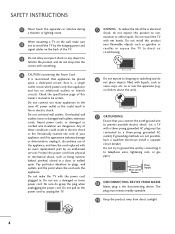
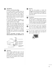
...not press strongly upon the panel with chemicals such as alcohol, thinners or benzene. 5 Do not spray water or other odors coming from the TV or hear strange sounds, unplug the power cord contact an authorized service center. Do not press against voltage surges and built-up static charges. ...antenna grounding If an outdoor antenna is grounded so as to provide some protection against or put stress on the front panel of the TV. 23 Ventilation Install your TV where there is turned off, unplugged and all cables have been removed. Do not install in a confined space such as a bookcase...
...not press strongly upon the panel with chemicals such as alcohol, thinners or benzene. 5 Do not spray water or other odors coming from the TV or hear strange sounds, unplug the power cord contact an authorized service center. Do not press against voltage surges and built-up static charges. ...antenna grounding If an outdoor antenna is grounded so as to provide some protection against or put stress on the front panel of the TV. 23 Ventilation Install your TV where there is turned off, unplugged and all cables have been removed. Do not install in a confined space such as a bookcase...
Owner's Manual
Page 6
... to prevent falling when the TV is used on a stand 17 Antenna or Cable Connection 18 EXTERNAL EQUIPMENT SETUP HD Receiver Setup 19 DVD Setup 22 VCR Setup 24 PC Setup 26 USB Connection 32 Other A/V Source Setup 32 Audio Out Connection 33 WATCHING TV / CHANNEL CONTROL Remote Control ...Functions 34 Turning On the TV 36 Channel Selection 36 Volume Adjustment 36 Quick Menu / Favorite Channel Setup 37 Initial...
... to prevent falling when the TV is used on a stand 17 Antenna or Cable Connection 18 EXTERNAL EQUIPMENT SETUP HD Receiver Setup 19 DVD Setup 22 VCR Setup 24 PC Setup 26 USB Connection 32 Other A/V Source Setup 32 Audio Out Connection 33 WATCHING TV / CHANNEL CONTROL Remote Control ...Functions 34 Turning On the TV 36 Channel Selection 36 Volume Adjustment 36 Quick Menu / Favorite Channel Setup 37 Initial...

Owner's Manual
Page 7
...Sleep Timer Setting 86 Auto Shut-off Setting 87 PARENTAL CONTROL / RATINGS Set Password & Lock System 88 Channel Blocking 91 Movie & TV Rating 92 Downloadable Rating 97 External Input Blocking 98 Key lock 99 APPENDIX Troubleshooting 100 Maintenance 102 Product Specifications 103 Programming the Remote ... Through RS-232C 109 Open Source License 116 7 Digital Broadcasting System Captions 81 - User Mode 72 Clear Voice 73 Balance 74 TV Speakers On/Off Setup 75 Audio Reset 76 Stereo/SAP Broadcast Setup 77 Audio Language 78 On-Screen Menus Language Selection 79 Caption ...
...Sleep Timer Setting 86 Auto Shut-off Setting 87 PARENTAL CONTROL / RATINGS Set Password & Lock System 88 Channel Blocking 91 Movie & TV Rating 92 Downloadable Rating 97 External Input Blocking 98 Key lock 99 APPENDIX Troubleshooting 100 Maintenance 102 Product Specifications 103 Programming the Remote ... Through RS-232C 109 Open Source License 116 7 Digital Broadcasting System Captions 81 - User Mode 72 Clear Voice 73 Balance 74 TV Speakers On/Off Setup 75 Audio Reset 76 Stereo/SAP Broadcast Setup 77 Audio Language 78 On-Screen Menus Language Selection 79 Caption ...

Owner's Manual
Page 8
... waste. This is normal, there is incorporated under license from SRS Labs, Inc. I Avoid touching the LCD screen or holding your local authority. 8 On Disposal (Only Hg lamp used LCD TV) The fluorescent lamp used in accordance to the touch, there may be a small "flicker" when it ...performance. "Dolby "and the double-D symbol are trademarks of mercury. FEATURE OF THIS TV is turned on. FOR LCD TV I Some minute dot defects may produce some temporary distortion effects on the screen. I If the TV feels cold to the regulations of your finger(s) against it is a trademark of ...
... waste. This is normal, there is incorporated under license from SRS Labs, Inc. I Avoid touching the LCD screen or holding your local authority. 8 On Disposal (Only Hg lamp used LCD TV) The fluorescent lamp used in accordance to the touch, there may be a small "flicker" when it ...performance. "Dolby "and the double-D symbol are trademarks of mercury. FEATURE OF THIS TV is turned on. FOR LCD TV I Some minute dot defects may produce some temporary distortion effects on the screen. I If the TV feels cold to the regulations of your finger(s) against it is a trademark of ...

Owner's Manual
Page 9
... all models.) (Refer to maintain standards compliance. CD Manual RETURN TV Q. MESNTUB MENU POWER DVD INPVUTCR ENTER VOL FAV AV MODE 1 4 MUTE 2 7 5 3 8 6 0 9 FLASHBK CH P A G E 1.5V 1.5V Remote Control, Batteries Power Cord (Only 32/37/42LG30DC) x4 x4 Bolts for stand assembly (Refer to P....13) (Only 32/37/42LG30DC) Screw for all models.) Option Extras D-sub 15 pin Cable When using the VGA (D-sub 15 pin...
... all models.) (Refer to maintain standards compliance. CD Manual RETURN TV Q. MESNTUB MENU POWER DVD INPVUTCR ENTER VOL FAV AV MODE 1 4 MUTE 2 7 5 3 8 6 0 9 FLASHBK CH P A G E 1.5V 1.5V Remote Control, Batteries Power Cord (Only 32/37/42LG30DC) x4 x4 Bolts for stand assembly (Refer to P....13) (Only 32/37/42LG30DC) Screw for all models.) Option Extras D-sub 15 pin Cable When using the VGA (D-sub 15 pin...

Owner's Manual
Page 10
... I NOTE: If your TV. And then wipe the TV with your TV, use it). G p.69) Remote Control Sensor POWER Button ENTER MENU INPUT CHANNEL ( , ) Buttons VOLUME (+, -) Buttons ENTER Button MENU Button INPUT Button 10 CH Intelligent Sensor (Except 32/37/42LG30DC) Adjusts picture according... to the surrounding conditions VOL Power/Standby Indicator Illuminates red in the OPTION menu. I Image shown may differ from your TV has a protection tape attached, remove the tape. ...
... I NOTE: If your TV. And then wipe the TV with your TV, use it). G p.69) Remote Control Sensor POWER Button ENTER MENU INPUT CHANNEL ( , ) Buttons VOLUME (+, -) Buttons ENTER Button MENU Button INPUT Button 10 CH Intelligent Sensor (Except 32/37/42LG30DC) Adjusts picture according... to the surrounding conditions VOL Power/Standby Indicator Illuminates red in the OPTION menu. I Image shown may differ from your TV has a protection tape attached, remove the tape. ...

Owner's Manual
Page 12
... jack for audio. 3 RGB (PC) Analog PC Connection. S-VIDEO Better quality than standard composition. Accepts DVI video using an adapter or HDMI to operate the TV on DC power. 12 Note: In standby mode, these ports do not work. 8 AUDIO OUT Analog audio output for use with AC power. Caution: Never...
... jack for audio. 3 RGB (PC) Analog PC Connection. S-VIDEO Better quality than standard composition. Accepts DVI video using an adapter or HDMI to operate the TV on DC power. 12 Note: In standby mode, these ports do not work. 8 AUDIO OUT Analog audio output for use with AC power. Caution: Never...

Owner's Manual
Page 13
... 2 Loose the bolts from your TV. COVER BASE 3 Assemble the TV as shown. 3 Detach the stand from TV. 4 Fix the 4 bolts securely using the holes in the back of the TV. Press the PROTECTION COVER into the TV until you hear it click. ! INSTALLATION (Only 32/37/42LG30DC) 1 Carefully place the TV screen side down on a cush...
... 2 Loose the bolts from your TV. COVER BASE 3 Assemble the TV as shown. 3 Detach the stand from TV. 4 Fix the 4 bolts securely using the holes in the back of the TV. Press the PROTECTION COVER into the TV until you hear it click. ! INSTALLATION (Only 32/37/42LG30DC) 1 Carefully place the TV screen side down on a cush...
Owner's Manual
Page 14
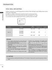
...or non specified wall mount is used . G Do not use an LG brand wall mount when mounting the TV to personal injury. LG is turned on a solid wall perpendicular to follow the TV installation instructions. A B Product LCD TV Model 32LG30DC 37LG30DC 42LG30DC 47LG50DC 52LG50DC VESA (A * B) 200 * 100 Standard Screw...dimensions for assembly are shown in severe personal injury. LG recommends that do not comply with the VESA standard screw specifications, the length of accidents. It may damage the TV or cause the TV to the TV. G Do not use fasten the screws too strongly,...
...or non specified wall mount is used . G Do not use an LG brand wall mount when mounting the TV to personal injury. LG is turned on a solid wall perpendicular to follow the TV installation instructions. A B Product LCD TV Model 32LG30DC 37LG30DC 42LG30DC 47LG50DC 52LG50DC VESA (A * B) 200 * 100 Standard Screw...dimensions for assembly are shown in severe personal injury. LG recommends that do not comply with the VESA standard screw specifications, the length of accidents. It may damage the TV or cause the TV to the TV. G Do not use fasten the screws too strongly,...
Owner's Manual
Page 15
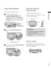
... 4 inches on all models.) DESKTOP PEDESTAL INSTALLATION I Image shown may differ from your TV. PREPARATION CABLE MANAGEMENT I Image shown may differ from your TV. 1 Connect the cables as necessary. SWIVEL STAND After installing the TV, you can adjust the TV set manually to suit your viewing position. 15 It will help prevent the power...
... 4 inches on all models.) DESKTOP PEDESTAL INSTALLATION I Image shown may differ from your TV. PREPARATION CABLE MANAGEMENT I Image shown may differ from your TV. 1 Connect the cables as necessary. SWIVEL STAND After installing the TV, you can adjust the TV set manually to suit your viewing position. 15 It will help prevent the power...

Owner's Manual
Page 16
...M5 x L (*L: Table depth + 8~10 mm) ex) Table depth: 15mm, Screw: M5 x 25 Only 32/37/42LG30DC Stand 1-Screw (provided as parts of the product) Desk WARNING G To prevent TV from falling over, the TV should be securely attached to a desk so it cannot be attached to the floor/wall per... installation instructions. PREPARATION PREPARATION ATTACHING THE TV TO A DESK The TV must be pulled in a forward/backward direction, potentially...
...M5 x L (*L: Table depth + 8~10 mm) ex) Table depth: 15mm, Screw: M5 x 25 Only 32/37/42LG30DC Stand 1-Screw (provided as parts of the product) Desk WARNING G To prevent TV from falling over, the TV should be securely attached to a desk so it cannot be attached to the floor/wall per... installation instructions. PREPARATION PREPARATION ATTACHING THE TV TO A DESK The TV must be pulled in a forward/backward direction, potentially...

Owner's Manual
Page 17
... rope so it cannot fall over if pushed backwards. I Use a sturdy rope or cord (sold separately) to the wall. G To use the TV safely make sure that the TV be attached to a wall so it cannot be pulled in a forward direction, potentially causing injury or damaging the product. Caution: Please make sure... shown may differ from falling off of the bracket on the wall and the one on or hang from the TV. Match the height of the TV. Ensure the eye-bolts or brackets are the same. 17 It is mounted on the wall to the holes in the product. Additionally, we recommend...
... rope so it cannot fall over if pushed backwards. I Use a sturdy rope or cord (sold separately) to the wall. G To use the TV safely make sure that the TV be attached to a wall so it cannot be pulled in a forward direction, potentially causing injury or damaging the product. Caution: Please make sure... shown may differ from falling off of the bracket on the wall and the one on or hang from the TV. Match the height of the TV. Ensure the eye-bolts or brackets are the same. 17 It is mounted on the wall to the holes in the product. Additionally, we recommend...

Owner's Manual
Page 18
... Connection. PREPARATION PREPARATION I To improve the picture quality in a poor signal area, please purchase a signal amplifier( a)nd install properly. ANTENNA OR CABLE CONNECTION 1. Cable Cable TV Wall Jack RF Coaxial Wire (75 ohm) ANTENNA/ CABLE IN I To prevent damage do not connect to bend the copper wire when connecting the antenna... wall antenna socket) R ANTENNA/ CABLE IN Outdoor Antenna (VHF, UHF) RF Coaxial Wire (75 ohm) R Single-family Dwellings /Houses (Connect to wall jack for two TV's, install a 2-Way Signal Splitter.
... Connection. PREPARATION PREPARATION I To improve the picture quality in a poor signal area, please purchase a signal amplifier( a)nd install properly. ANTENNA OR CABLE CONNECTION 1. Cable Cable TV Wall Jack RF Coaxial Wire (75 ohm) ANTENNA/ CABLE IN I To prevent damage do not connect to bend the copper wire when connecting the antenna... wall antenna socket) R ANTENNA/ CABLE IN Outdoor Antenna (VHF, UHF) RF Coaxial Wire (75 ohm) R Single-family Dwellings /Houses (Connect to wall jack for two TV's, install a 2-Way Signal Splitter.

Owner's Manual
Page 19
..., PB = blue, and PR = red). Y PB PR L R 2 Connect the audio output of the digital settop box to use I Turn on the TV. 2. EXTERNAL EQUIPMENT SETUP EXTERNAL EQUIPMENT SETUP I To prevent the equipment damage, never plug in any power cords until you do receive digital signals from your...finished connecting all equipment. I Image shown may differ from a digital set -top box. (Refer to COMPONENT IN2 input, select the Component 2 input source on the TV. 1 2 RGB IN RGB(PC) AUDIO REMOTE (RGB/DVI) CONTROL IN DVI IN (CO 2 AV IN 1 Y 1 PB PR L R VIDEO AUDIO COMPONENT...
..., PB = blue, and PR = red). Y PB PR L R 2 Connect the audio output of the digital settop box to use I Turn on the TV. 2. EXTERNAL EQUIPMENT SETUP EXTERNAL EQUIPMENT SETUP I To prevent the equipment damage, never plug in any power cords until you do receive digital signals from your...finished connecting all equipment. I Image shown may differ from a digital set -top box. (Refer to COMPONENT IN2 input, select the Component 2 input source on the TV. 1 2 RGB IN RGB(PC) AUDIO REMOTE (RGB/DVI) CONTROL IN DVI IN (CO 2 AV IN 1 Y 1 PB PR L R VIDEO AUDIO COMPONENT...
Owner's Manual
Page 20
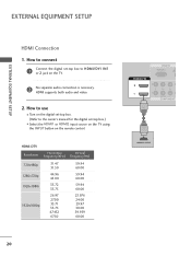
... the digital set -top box to connect 1 Connect the digital set -top box.) I Select the HDMI1 or HDMI2 input source on the TV using the INPUT button on the TV. 2 No separate audio connection is necessary. HDMI supports both audio and video. 2. How to HDMI/DVI IN1 or 2 jack on the remote...
... the digital set -top box to connect 1 Connect the digital set -top box.) I Select the HDMI1 or HDMI2 input source on the TV using the INPUT button on the TV. 2 No separate audio connection is necessary. HDMI supports both audio and video. 2. How to HDMI/DVI IN1 or 2 jack on the remote...
Owner's Manual
Page 21
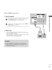
... PR L R VIDEO AUDIO COMPONENT IN 2 1 DVI-DTV OUTPUT L R 21 NOTE G A DVI to the A U D I Select the HDMI1 or HDMI2 input source on the TV using the INPUT button on the TV. 2. DVI doesn't support audio, so a separate audio connection is required for the digital set -top box to the HDMI/DVI IN 1 or... 2 jack on the TV. 2 Connect the PC audio output to HDMI cable or adapter is necessary. How to use I Turn on the digital set-top box. (Refer to the ...
... PR L R VIDEO AUDIO COMPONENT IN 2 1 DVI-DTV OUTPUT L R 21 NOTE G A DVI to the A U D I Select the HDMI1 or HDMI2 input source on the TV using the INPUT button on the TV. 2. DVI doesn't support audio, so a separate audio connection is required for the digital set -top box to the HDMI/DVI IN 1 or... 2 jack on the TV. 2 Connect the PC audio output to HDMI cable or adapter is necessary. How to use I Turn on the digital set-top box. (Refer to the ...

Owner's Manual
Page 22
...the video outputs (Y, PB, PR) of the DVD to the component input ports as shown below. Component ports on the TV Y Y Video output ports Y on the remote control. I Turn on the TV. Match the jack colors (Y = green, PB = blue, and PR = red). Y PB PR L R 2 ...R VIDEO AUDIO COMPONENT IN Component Input ports To get better picture quality, connect a DVD player to the COMPONENT IN AUDIO1 jacks on the TV. EXTERNAL EQUIPMENT SETUP EXTERNAL EQUIPMENT SETUP DVD SETUP Component Connection 1. I If connected to COMPONENT IN 2 input, select the Component 2 input source on ...
...the video outputs (Y, PB, PR) of the DVD to the component input ports as shown below. Component ports on the TV Y Y Video output ports Y on the remote control. I Turn on the TV. Match the jack colors (Y = green, PB = blue, and PR = red). Y PB PR L R 2 ...R VIDEO AUDIO COMPONENT IN Component Input ports To get better picture quality, connect a DVD player to the COMPONENT IN AUDIO1 jacks on the TV. EXTERNAL EQUIPMENT SETUP EXTERNAL EQUIPMENT SETUP DVD SETUP Component Connection 1. I If connected to COMPONENT IN 2 input, select the Component 2 input source on ...


