
Owner's Manual (English)
Page 3
... wipe stained spot on the surface of the exterior. TV Brackets, 2- TV Bracket 2- Wall Brackets 2-eye-bolts 2- tact the dealer where you purchased the product. Wall Brackets 60PY3DF* only 1-screw for stand fixing Refer to p. 16 42/50PB4D* only This feature is not available for all ...available for all models. 32LB9D* only Cable Management 50/60PY3DF* only Twist Holder Arrange the wires with 2- I /II TIME USB SLEEP Remote Control Power Cord Polishing Cloth This feature is not available for stand assembly Refer to p. 9 50PY3DF* only Additional Cover Refer to p. 16...
... wipe stained spot on the surface of the exterior. TV Brackets, 2- TV Bracket 2- Wall Brackets 2-eye-bolts 2- tact the dealer where you purchased the product. Wall Brackets 60PY3DF* only 1-screw for stand fixing Refer to p. 16 42/50PB4D* only This feature is not available for all ...available for all models. 32LB9D* only Cable Management 50/60PY3DF* only Twist Holder Arrange the wires with 2- I /II TIME USB SLEEP Remote Control Power Cord Polishing Cloth This feature is not available for stand assembly Refer to p. 9 50PY3DF* only Additional Cover Refer to p. 16...

Owner's Manual (English)
Page 4
... for PC Mode 29 USB In Setup 31 AV Output Setup 32 Digital Audio Output Setup 33 WATCHING TV / PROGRAMME CONTROL Remote Control Key Functions 34 Turning on the TV 36 Initializing Setup 36 Programme Selection 37 Volume Adjustment 37 On-Screen Menus Selection and Adjustment . . ...38 Factory Reset 39 Model Info 39 Auto Programme Tuning 40 Manual Programme Tuning 42 Fine Tuning 44 Assigning a Station Name...
... for PC Mode 29 USB In Setup 31 AV Output Setup 32 Digital Audio Output Setup 33 WATCHING TV / PROGRAMME CONTROL Remote Control Key Functions 34 Turning on the TV 36 Initializing Setup 36 Programme Selection 37 Volume Adjustment 37 On-Screen Menus Selection and Adjustment . . ...38 Factory Reset 39 Model Info 39 Auto Programme Tuning 40 Manual Programme Tuning 42 Fine Tuning 44 Assigning a Station Name...
Owner's Manual (English)
Page 5
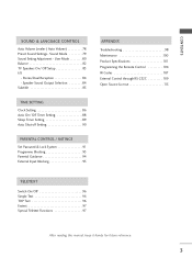
... Set Password & Lock System 91 Programme Blocking 93 Parental Guidance 94 External Input Blocking 95 APPENDIX Troubleshooting 98 Maintenance 100 Product Specifications 101 Programming the Remote Control 104 IR Codes 107 External Control through RS-232C 109 Open Source License 115 TELETEXT Switch On/Off 96 Simple Text 96 TOP Text... 96 Fastext 97 Special Teletext Functions 97 After reading this manual, keep it handy for future reference. 3 User Mode 80 Balance 82 TV Speakers On/ Off Setup 83 I/II -
... Set Password & Lock System 91 Programme Blocking 93 Parental Guidance 94 External Input Blocking 95 APPENDIX Troubleshooting 98 Maintenance 100 Product Specifications 101 Programming the Remote Control 104 IR Codes 107 External Control through RS-232C 109 Open Source License 115 TELETEXT Switch On/Off 96 Simple Text 96 TOP Text... 96 Fastext 97 Special Teletext Functions 97 After reading this manual, keep it handy for future reference. 3 User Mode 80 Balance 82 TV Speakers On/ Off Setup 83 I/II -

Owner's Manual (English)
Page 6
PREPARATION FRONT PANEL CONTROLS I If your TV. INPUT Button POWER Button OK Button VOLUME MENU Button (F,G) Buttons PROGRAMME (E,D) Buttons 4 Image shown may be somewhat different from your product has a protection film attached, remove the film and then wipe the product with a polishing cloth. 50/60PY3DF* PREPARATION Remote Control Sensor Program Display INPUT MENU...
PREPARATION FRONT PANEL CONTROLS I If your TV. INPUT Button POWER Button OK Button VOLUME MENU Button (F,G) Buttons PROGRAMME (E,D) Buttons 4 Image shown may be somewhat different from your product has a protection film attached, remove the film and then wipe the product with a polishing cloth. 50/60PY3DF* PREPARATION Remote Control Sensor Program Display INPUT MENU...

Owner's Manual (English)
Page 7
PREPARATION 42/50PB4D* Remote Control Sensor Power/Standby Indicator • illuminates red in standby mode. • illuminates green when the set is switched on . POWER Button Remote Control Power/Standby Indicator Sensor • illuminates red in standby mode. • illuminates green ...when the set is switched on . 5 INPUT MENU OK VOL PR INPUT MENU OK VOL PR POWER Button INPUT Button MENU Button OK Button VOLUME Buttons PROGRAMME Buttons 42...
PREPARATION 42/50PB4D* Remote Control Sensor Power/Standby Indicator • illuminates red in standby mode. • illuminates green when the set is switched on . POWER Button Remote Control Power/Standby Indicator Sensor • illuminates red in standby mode. • illuminates green ...when the set is switched on . 5 INPUT MENU OK VOL PR INPUT MENU OK VOL PR POWER Button INPUT Button MENU Button OK Button VOLUME Buttons PROGRAMME Buttons 42...

Owner's Manual (English)
Page 9
...equipment. PREPARATION 1 HDMI/DVI IN 3 2 1 2 RGB IN RGB (PC) AUDIO (RGB/DVI) COMPONENT IN 34 5 6 ANTENNA IN DIGITAL AUDIO OUT REMOTE CONTROL IN OPTICAL VIDEO RS-232C IN (CONTROL & SERVICE) AV OUT AUDIO AV IN 1 S-VIDEO VIDEO 7 AUDIO VIDEO (MONO) AUDIO 89 1 HDMI/...operation with a HDMI to this port with AC power. AUDIO OUT REMOTE CONTROL IN OPTICAL VIDEO 9 AV OUT AV OUT 4 Remote Control Port COMPONENT IN ConRnS-2e32cCtINa second TV or monitor. (CONTROL & SERVICE) Connect your wired remote control. 10 Power Cord Socket 5 ANTENNA IN Connect antenna signals to ...
...equipment. PREPARATION 1 HDMI/DVI IN 3 2 1 2 RGB IN RGB (PC) AUDIO (RGB/DVI) COMPONENT IN 34 5 6 ANTENNA IN DIGITAL AUDIO OUT REMOTE CONTROL IN OPTICAL VIDEO RS-232C IN (CONTROL & SERVICE) AV OUT AUDIO AV IN 1 S-VIDEO VIDEO 7 AUDIO VIDEO (MONO) AUDIO 89 1 HDMI/...operation with a HDMI to this port with AC power. AUDIO OUT REMOTE CONTROL IN OPTICAL VIDEO 9 AV OUT AV OUT 4 Remote Control Port COMPONENT IN ConRnS-2e32cCtINa second TV or monitor. (CONTROL & SERVICE) Connect your wired remote control. 10 Power Cord Socket 5 ANTENNA IN Connect antenna signals to ...

Owner's Manual (English)
Page 10
... a set top box or PC to the RS-232C port on DC REMOTE CONTROL IN OPTICAL VIDEO AV OUT 6 DIGITAL AUDIO OUT Connect digital audio from various types of COMPONENT IN equipment. LCD TV Models 42/47/52LB9DF* USB IN S-VIDEO USB IN 32LB9D* USB IN S-VIDEO ...USB Input S-VIDEO Input Connect S-Video out from an S-VIDEO device. PREPARATION PREPARATION I Image shown may be somewhat different from your wired remote control. 10 Power Cord Socket ...
... a set top box or PC to the RS-232C port on DC REMOTE CONTROL IN OPTICAL VIDEO AV OUT 6 DIGITAL AUDIO OUT Connect digital audio from various types of COMPONENT IN equipment. LCD TV Models 42/47/52LB9DF* USB IN S-VIDEO USB IN 32LB9D* USB IN S-VIDEO ...USB Input S-VIDEO Input Connect S-Video out from an S-VIDEO device. PREPARATION PREPARATION I Image shown may be somewhat different from your wired remote control. 10 Power Cord Socket ...
Owner's Manual (English)
Page 20
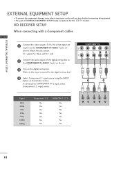
..., PR) of the digital set top box to COMPONENT IN 2 input, select Component 2 input source. If connected to the COMPONENT IN VIDEO 1 jacks on the remote control. Match the jack colours. (Y = green, PB = blue, and PR = red) 2 Connect the audio output of the digital set-top box to the COMPONENT IN... AUDIO 1 jacks on the set. 3 Turn on the digital set-top box. (Refer to the owner's manual for the LCD TV models. COMPONENT IN VIDEO AUDIO 1 2 Signal 480i 480p 576i 576p 720p 1080i 1080p Component 1/2 Yes Yes Yes Yes Yes Yes Yes HDMI/DVI 1, 2, 3 No Yes...
..., PR) of the digital set top box to COMPONENT IN 2 input, select Component 2 input source. If connected to the COMPONENT IN VIDEO 1 jacks on the remote control. Match the jack colours. (Y = green, PB = blue, and PR = red) 2 Connect the audio output of the digital set-top box to the COMPONENT IN... AUDIO 1 jacks on the set. 3 Turn on the digital set-top box. (Refer to the owner's manual for the LCD TV models. COMPONENT IN VIDEO AUDIO 1 2 Signal 480i 480p 576i 576p 720p 1080i 1080p Component 1/2 Yes Yes Yes Yes Yes Yes Yes HDMI/DVI 1, 2, 3 No Yes...
Owner's Manual (English)
Page 21
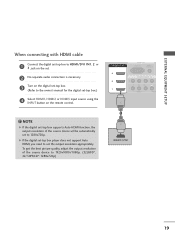
... connection is necessary. To get the best picture quality, adjust the output resolution of the source device will be automatically set to 1920x1080i/1080p. (32LB9D*, 42/50PB4D*: 1280x720p) 1 HDMI-DTV OUTPUT 19 NOTE G If the digital set-top box supports Auto HDMI function, the output resolution of the source device to... input source using the INPUT button on the digital set-top box. (Refer to the owner's manual for the digital set . AUDIO 2 3 Turn on the remote control. !
... connection is necessary. To get the best picture quality, adjust the output resolution of the source device will be automatically set to 1920x1080i/1080p. (32LB9D*, 42/50PB4D*: 1280x720p) 1 HDMI-DTV OUTPUT 19 NOTE G If the digital set-top box supports Auto HDMI function, the output resolution of the source device to... input source using the INPUT button on the digital set-top box. (Refer to the owner's manual for the digital set . AUDIO 2 3 Turn on the remote control. !
Owner's Manual (English)
Page 22
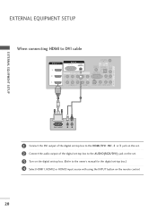
... EQUIPMENT SETUP EXTERNAL EQUIPMENT SETUP When connecting HDMI to DVI cable HDMI/DVI IN 3 2 1 RGB IN RGB (PC) AUDIO (RGB/DVI) COMPONENT IN ANTENNA IN REMOTE CONTROL IN DIGITAL AUDIO OUT OPTICAL VIDEO RS-232C IN (CONTROL & SERVICE) AUDIO VIDEO AUDIO S-VIDEO VIDEO (MONO) AUDIO 1 2 AV OUT AV IN 1 DVI-DTV.... (Refer to the owner's manual for the digital set-top box.) 4 Select HDMI1, HDMI2 or HDMI3 input source with using the INPUT button on the remote control. 20
... EQUIPMENT SETUP EXTERNAL EQUIPMENT SETUP When connecting HDMI to DVI cable HDMI/DVI IN 3 2 1 RGB IN RGB (PC) AUDIO (RGB/DVI) COMPONENT IN ANTENNA IN REMOTE CONTROL IN DIGITAL AUDIO OUT OPTICAL VIDEO RS-232C IN (CONTROL & SERVICE) AUDIO VIDEO AUDIO S-VIDEO VIDEO (MONO) AUDIO 1 2 AV OUT AV IN 1 DVI-DTV.... (Refer to the owner's manual for the digital set-top box.) 4 Select HDMI1, HDMI2 or HDMI3 input source with using the INPUT button on the remote control. 20

Owner's Manual (English)
Page 23
... Component 1 input source using the INPUT button on DVD player Y PB PR Y B-Y R-Y Y Cb Cr Y Pb Pr 21 Component ports on the TV Y PB PR Video output ports on the remote control. If connected to COMPONENT IN 2 input, select Component 2 input source. 5 Refer to the component input ports as shown below. EXTERNAL EQUIPMENT...
... Component 1 input source using the INPUT button on DVD player Y PB PR Y B-Y R-Y Y Cb Cr Y Pb Pr 21 Component ports on the TV Y PB PR Video output ports on the remote control. If connected to COMPONENT IN 2 input, select Component 2 input source. 5 Refer to the component input ports as shown below. EXTERNAL EQUIPMENT...
Owner's Manual (English)
Page 24
... be automatically set to set . 3 Turn on the DVD player, insert a DVD. 4 Select A V 1 input source using the INPUT button on the remote control. 4 Refer to the S-VIDEO input on the remote control. If connected to AV IN 2 input, select A V 2 input source.(Except 32LB9D*) 5 Refer to the AUDIO input jacks on the set...
... be automatically set to set . 3 Turn on the DVD player, insert a DVD. 4 Select A V 1 input source using the INPUT button on the remote control. 4 Refer to the S-VIDEO input on the remote control. If connected to AV IN 2 input, select A V 2 input source.(Except 32LB9D*) 5 Refer to the AUDIO input jacks on the set...

Owner's Manual (English)
Page 25
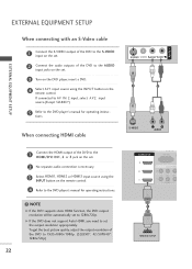
... IN RGB When connecting with an antenna C 2 EXTERNAL EQUIPMENT SETUP HDMI/DVI IN 2 1 (DVI) RGB IN RGB (PC) AUDIO (RGB/DVI) COMPONENT IN ANTENNA IN REMOTE CONTROL IN DIGITAL AUDIO OUT OPTICAL VIDEO RS-232C IN (CONTROL & SERVICE) AUDIO VIDEO AUDIO S-VIDEO VIDEO (MONO) AUDIO AV IN 1 AV OUT 1 ANT OUT...SETUP I If the 4:3 picture format is common to all manufacturers and in socket of the VCR. 3 Set VCR output switch to 3 or 4 and then tune TV to the same programme number. 4 Insert a video tape into the VCR and press PLAY on the screen. the fixed images on the sides of the...
... IN RGB When connecting with an antenna C 2 EXTERNAL EQUIPMENT SETUP HDMI/DVI IN 2 1 (DVI) RGB IN RGB (PC) AUDIO (RGB/DVI) COMPONENT IN ANTENNA IN REMOTE CONTROL IN DIGITAL AUDIO OUT OPTICAL VIDEO RS-232C IN (CONTROL & SERVICE) AUDIO VIDEO AUDIO S-VIDEO VIDEO (MONO) AUDIO AV IN 1 AV OUT 1 ANT OUT...SETUP I If the 4:3 picture format is common to all manufacturers and in socket of the VCR. 3 Set VCR output switch to 3 or 4 and then tune TV to the same programme number. 4 Insert a video tape into the VCR and press PLAY on the screen. the fixed images on the sides of the...

Owner's Manual (English)
Page 26
...the S-VIDEO output of the set. COMPONENT IN 2 When connecting with an RCA cable 1 (DVI) VIDEO AUDIO 1 Connect the AUDIO/VIDEO jacks between TV and VCR. NOTE G The picture quality is improved: ; compared to AV IN2, select A V 2 input source. ! In the event that you...VCR to the VCR owner's manual.) 4 SeleCctOAMVPO1NinEpNuTtINsource using the INPUT button on 2 the remote control. If connected to the VCR owner's manual.) 1 3 Select A V 1 input source using the INPUT button on the remote control. Match the jack colours(Video = yellow, Audio Left = white, and Audio ...
...the S-VIDEO output of the set. COMPONENT IN 2 When connecting with an RCA cable 1 (DVI) VIDEO AUDIO 1 Connect the AUDIO/VIDEO jacks between TV and VCR. NOTE G The picture quality is improved: ; compared to AV IN2, select A V 2 input source. ! In the event that you...VCR to the VCR owner's manual.) 4 SeleCctOAMVPO1NinEpNuTtINsource using the INPUT button on 2 the remote control. If connected to the VCR owner's manual.) 1 3 Select A V 1 input source using the INPUT button on the remote control. Match the jack colours(Video = yellow, Audio Left = white, and Audio ...

Owner's Manual (English)
Page 27
If connected to AV IN1 input, select AV1 input source. 3 Operate the corresponding external equipment. 25 EXTERNAL EQUIPMENT SETUP OTHER A/V SOURCE SETUP 32 inches 42/47/50/52/60 inches USB IN USB IN VIDEO L/MONO AUDIO R 1 AV IN 2 VIDEO L/MONO AUDIO R S-VIDEO 1 AV IN 2 VIDEO L R Camcorder Video Game Set VIDEO L R Camcorder Video Game Set 1 Connect the AUDIO/VIDEO jacks between TV and external equipment. Match the jack colours.(Video = yellow, Audio Left = white, and Audio Right = red) 2 Select AV2 input source using the INPUT button on the remote control.
If connected to AV IN1 input, select AV1 input source. 3 Operate the corresponding external equipment. 25 EXTERNAL EQUIPMENT SETUP OTHER A/V SOURCE SETUP 32 inches 42/47/50/52/60 inches USB IN USB IN VIDEO L/MONO AUDIO R 1 AV IN 2 VIDEO L/MONO AUDIO R S-VIDEO 1 AV IN 2 VIDEO L R Camcorder Video Game Set VIDEO L R Camcorder Video Game Set 1 Connect the AUDIO/VIDEO jacks between TV and external equipment. Match the jack colours.(Video = yellow, Audio Left = white, and Audio Right = red) 2 Select AV2 input source using the INPUT button on the remote control.

Owner's Manual (English)
Page 28
..., change the PC graphic card or consult the manufacturer of the PC graphic card. RGB IN RGB (PC) AUDIO (RGB/DVI) COMPONENT IN ANTEN IN REMOTE CONTROL IN DIGITAL AUDIO OUT OPTICA RS-232C IN (CONTROL & SERVICE) VIDEO AUDIO S-VIDEO VIDEO (MON 1 2 ! When connecting D-sub 15pin cable RGB...brightness and contrast on the VIDEO menu until the picture is clear. EXTERNAL EQUIPMENT SETUP EXTERNAL EQUIPMENT SETUP PC SETUP This TV provides Plug and Play capability, meaning that the PC adjusts automatically to another resolution, change the screen scanning rate for this purpose.
..., change the PC graphic card or consult the manufacturer of the PC graphic card. RGB IN RGB (PC) AUDIO (RGB/DVI) COMPONENT IN ANTEN IN REMOTE CONTROL IN DIGITAL AUDIO OUT OPTICA RS-232C IN (CONTROL & SERVICE) VIDEO AUDIO S-VIDEO VIDEO (MON 1 2 ! When connecting D-sub 15pin cable RGB...brightness and contrast on the VIDEO menu until the picture is clear. EXTERNAL EQUIPMENT SETUP EXTERNAL EQUIPMENT SETUP PC SETUP This TV provides Plug and Play capability, meaning that the PC adjusts automatically to another resolution, change the screen scanning rate for this purpose.

Owner's Manual (English)
Page 29
...When connecting HDMI to DVI cable HDMI/DVI IN 3 2 1 RGB IN RGB (PC) AUDIO (RGB/DVI) COMPONENT IN ANTENNA IN REMOTE CONTROL IN DIGITAL AUDIO OUT OPTICAL VIDEO RS-232C IN (CONTROL & SERVICE) AUDIO VIDEO AUDIO S-VIDEO VIDEO (MONO) AUDIO 1 2... DVI-PC OUTPUT L R 1 Connect the DVI output of the PC to the HDMI/DVI IN1, 2 or 3 jack on the remote control. ! G If the PC does not support Auto DVI, you need to the AUDIO (RGB/DVI) jack on the set. ... quality, adjust the PC graphics card's output resolution to 1920x1080, 60Hz. (42PB4D* : 1024x768p, 32LB9D*/50PB4D*: 1360x768p) 27
...When connecting HDMI to DVI cable HDMI/DVI IN 3 2 1 RGB IN RGB (PC) AUDIO (RGB/DVI) COMPONENT IN ANTENNA IN REMOTE CONTROL IN DIGITAL AUDIO OUT OPTICAL VIDEO RS-232C IN (CONTROL & SERVICE) AUDIO VIDEO AUDIO S-VIDEO VIDEO (MONO) AUDIO 1 2... DVI-PC OUTPUT L R 1 Connect the DVI output of the PC to the HDMI/DVI IN1, 2 or 3 jack on the remote control. ! G If the PC does not support Auto DVI, you need to the AUDIO (RGB/DVI) jack on the set. ... quality, adjust the PC graphics card's output resolution to 1920x1080, 60Hz. (42PB4D* : 1024x768p, 32LB9D*/50PB4D*: 1360x768p) 27

Owner's Manual (English)
Page 31
... G button and then use D or E button to select Screen. 3 Press the G button to a PC Output, Select RGB-PC with using the INPUT button on the remote control. EXTERNAL EQUIPMENT SETUP Screen Setup for PC mode Overview When the RGB input, of the set is connected to enter the screen adjustment menu.
... G button and then use D or E button to select Screen. 3 Press the G button to a PC Output, Select RGB-PC with using the INPUT button on the remote control. EXTERNAL EQUIPMENT SETUP Screen Setup for PC mode Overview When the RGB input, of the set is connected to enter the screen adjustment menu.

Owner's Manual (English)
Page 34
...be used for fur1th(DeVrI) details regarding that device's input settings. G We recommend to hook up a second TV or monitor. EXTERNAL EQUIPMENT SETUP EXTERNAL EQUIPMENT SETUP AV OUTPUT SETUP The TV has a special signal output capability which allows you to use the AV OUT jacks for VCR recording. 1 VIDEO... L R S-VIDEO 32 AV IN 1 AV OUT HDMI/DVI IN RGB IN RGB (PC) 1 Connect the second TV or monitor to the TV's AV OUT jacks. VIDEO AUDIO REMOTE ONTROL IN DIGITAL AUDIO OUT OPTICAL VIDEO RS-232C IN TROL & SERVICE) AUDIO IDEO VIDEO (MONO) AUDIO !
...be used for fur1th(DeVrI) details regarding that device's input settings. G We recommend to hook up a second TV or monitor. EXTERNAL EQUIPMENT SETUP EXTERNAL EQUIPMENT SETUP AV OUTPUT SETUP The TV has a special signal output capability which allows you to use the AV OUT jacks for VCR recording. 1 VIDEO... L R S-VIDEO 32 AV IN 1 AV OUT HDMI/DVI IN RGB IN RGB (PC) 1 Connect the second TV or monitor to the TV's AV OUT jacks. VIDEO AUDIO REMOTE ONTROL IN DIGITAL AUDIO OUT OPTICAL VIDEO RS-232C IN TROL & SERVICE) AUDIO IDEO VIDEO (MONO) AUDIO !

Owner's Manual (English)
Page 35
COMPONENT IN 2 2 Connect the other end of an optical cable to the digi- See the external audio equipment instruction manual for operation. REMOTE CONTROL IN DIGITAL AUDIO OUT OPTICAL VIDEO RS-232C IN (CONTROL & SERVICE) 1 AUDIO S-VIDEO VIDEO (MONO) AUDIO 2 ! Looking at the laser ...beam may damage your vision. 33 NOTE G When connecting with external audio equipments, such as amplifiers or speakers, please turn the TV speakers off. Off" in the AUDIO menu. CAUTION G Do not look into the optical output port. tal audio (optical) input on the audio equipment....
COMPONENT IN 2 2 Connect the other end of an optical cable to the digi- See the external audio equipment instruction manual for operation. REMOTE CONTROL IN DIGITAL AUDIO OUT OPTICAL VIDEO RS-232C IN (CONTROL & SERVICE) 1 AUDIO S-VIDEO VIDEO (MONO) AUDIO 2 ! Looking at the laser ...beam may damage your vision. 33 NOTE G When connecting with external audio equipments, such as amplifiers or speakers, please turn the TV speakers off. Off" in the AUDIO menu. CAUTION G Do not look into the optical output port. tal audio (optical) input on the audio equipment....


