
Service Manual
Page 4
...-3-1. OUT ...14 8. TEST 7 GAS VALVE TEST - CHANGE GAS SETTING (NATURAL GAS, PROPANE GAS 24 11. MOTOR DIAGRAM AND SCHEMATIC 13 7. TEST 1 120VAC ELECTRICAL SUPPLY 17 9-2. DISASSEMBLY INSTRUCTIONS 26 12. COLUMBUS DRYER CYCLE PROCESS 9 5. GAS TYPE 23 10. DIAGNOSTIC TEST ...16 9-1. TEST 6 HEATER SWITCH TEST - CONTENTS 1. COMPONENT TESTING INFORMATION 10 6. TEST 3 MOTOR...
...-3-1. OUT ...14 8. TEST 7 GAS VALVE TEST - CHANGE GAS SETTING (NATURAL GAS, PROPANE GAS 24 11. MOTOR DIAGRAM AND SCHEMATIC 13 7. TEST 1 120VAC ELECTRICAL SUPPLY 17 9-2. DISASSEMBLY INSTRUCTIONS 26 12. COLUMBUS DRYER CYCLE PROCESS 9 5. GAS TYPE 23 10. DIAGNOSTIC TEST ...16 9-1. TEST 6 HEATER SWITCH TEST - CONTENTS 1. COMPONENT TESTING INFORMATION 10 6. TEST 3 MOTOR...

Service Manual
Page 25
... with Propane Gas orifice. STEP 1 : VALVE SETTING Full open "Change screw" STEP 2 : ORIFICE CHANGE Orifice Close "Change screw" Remove 2 screws. Propane Gas Orifice is set. Disassemble the pipe assembly. Initially, Natural Gas mode is on sale as a Service Part to authorized servicers only. Conversion must be made by a qualified technician. Gas...
... with Propane Gas orifice. STEP 1 : VALVE SETTING Full open "Change screw" STEP 2 : ORIFICE CHANGE Orifice Close "Change screw" Remove 2 screws. Propane Gas Orifice is set. Disassemble the pipe assembly. Initially, Natural Gas mode is on sale as a Service Part to authorized servicers only. Conversion must be made by a qualified technician. Gas...

Service Manual
Page 27
Pull the control panel forward. 3. Open the cover protect. 4. Remove 5 screws. 6. Disassemble the controller assembly. 26 Disconnect connectors. 5. 11 DISASSEMBLY INSTRUCTIONS Disassemble and repair the unit only after pulling out power plug from the outlet. 1. Remove 3 screws on the rear Panel. 2.
Pull the control panel forward. 3. Open the cover protect. 4. Remove 5 screws. 6. Disassemble the controller assembly. 26 Disconnect connectors. 5. 11 DISASSEMBLY INSTRUCTIONS Disassemble and repair the unit only after pulling out power plug from the outlet. 1. Remove 3 screws on the rear Panel. 2.
Service Manual
Page 29
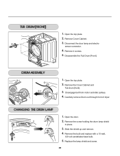
... 4 screws. 5. Disengage belt from motor and idler pulleys. 4. Slide the shield up and remove. 4. Replace the lamp shield and screw. 28 Open the top plate. 2. Disassemble the Tub Drum [Front]. -1 1. Remove the Cover Cabinet and Tub drum [front]. -2 3. Open the top plate. -1 2. Open the door. 2. 1. Remove the screw holding the drum...
... 4 screws. 5. Disengage belt from motor and idler pulleys. 4. Slide the shield up and remove. 4. Replace the lamp shield and screw. 28 Open the top plate. 2. Disassemble the Tub Drum [Front]. -1 1. Remove the Cover Cabinet and Tub drum [front]. -2 3. Open the top plate. -1 2. Open the door. 2. 1. Remove the screw holding the drum...


