
Owner's Manual
Page 5
PREPARATION STAND INSTALLATION I The image shown may be somewhat different from your set. 1 Carefully place the product screen side down on a cushioned surface that will protect product and screen from damage. 2 Insert the Stand Base into the product. Stand Base 3 Turn the Stand Base Lock through 90° to fix the stand base to the stand body. OPEN OPEN OPEN OPEN Stand Base Lock 4 5 3
PREPARATION STAND INSTALLATION I The image shown may be somewhat different from your set. 1 Carefully place the product screen side down on a cushioned surface that will protect product and screen from damage. 2 Insert the Stand Base into the product. Stand Base 3 Turn the Stand Base Lock through 90° to fix the stand base to the stand body. OPEN OPEN OPEN OPEN Stand Base Lock 4 5 3

Owner's Manual
Page 7
Stand Base 3 Turn the Stand Base Lock through 90° to the left. OPEN OPEN Latch 5 PREPARATION DETACHING STAND I The image shown may be somewhat different from your monitor. 1 Place the set screen side down on a cushion or soft cloth. 2 Detach the monitor to the Stand Base by turning the screw to separate the stand base from stand body. OPEN OPEN OPEN OPEN 4 Pushing Latch inside, Take the stand base from the stand body.
Stand Base 3 Turn the Stand Base Lock through 90° to the left. OPEN OPEN Latch 5 PREPARATION DETACHING STAND I The image shown may be somewhat different from your monitor. 1 Place the set screen side down on a cushion or soft cloth. 2 Detach the monitor to the Stand Base by turning the screw to separate the stand base from stand body. OPEN OPEN OPEN OPEN 4 Pushing Latch inside, Take the stand base from the stand body.
Owner's Manual
Page 11
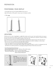
... should be taken not to follow these instructions. < Screw Mounting Interface Dimension > M2262D/M2362D/M2362DP : 100 mm x 100 mm hole spacing M2762D/M2762DP : 200 mm x 100 mm hole spacing * Wall mount interface(LG) : RW120 RW240 Warning: When adjusting the angle of the monitor and the stand body. Do not cover the ventilation...
... should be taken not to follow these instructions. < Screw Mounting Interface Dimension > M2262D/M2362D/M2362DP : 100 mm x 100 mm hole spacing M2762D/M2762DP : 200 mm x 100 mm hole spacing * Wall mount interface(LG) : RW120 RW240 Warning: When adjusting the angle of the monitor and the stand body. Do not cover the ventilation...
Owner's Manual
Page 28
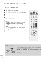
Note: a. I Open the battery compartment cover on the back and install the batteries matching correct polarity (+ with +, - POWER TV/PC INPUT PICTURE SOUND SAP RATIO 123 4 56 ...
Note: a. I Open the battery compartment cover on the back and install the batteries matching correct polarity (+ with +, - POWER TV/PC INPUT PICTURE SOUND SAP RATIO 123 4 56 ...

Owner's Manual
Page 94
... actual digital channel number, the Major is the number that the channel should be mapped to the Major number, the Physical number is released. 14. I Open the battery compartment cover on the set Acknowledgement [u][ ][Set ID][ ][OK/NG][Data][x] *Real data mapping 0 : Step 0 A : Step 10 (SET ID 10) F : Step 15 (SET...
... actual digital channel number, the Major is the number that the channel should be mapped to the Major number, the Physical number is released. 14. I Open the battery compartment cover on the set Acknowledgement [u][ ][Set ID][ ][OK/NG][Data][x] *Real data mapping 0 : Step 0 A : Step 10 (SET ID 10) F : Step 15 (SET...


