Specification (English)
Page 1
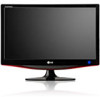
...dynamic contrast ratio deliver image quality and precision until now only found on the promise of computer and home entertainment convergence is the M237WD Monitor/ Television. Incorporating a full compliment of television and computer connectivity into a stylish 1080p Full HD display, the M237WD provides perfect balance... XT CONNECTIVITY • 2 HDMI™ • 1 Component Video • 1 Composite Video • 1 S-Video • D-Sub • DVI-D LGusa.com MONITORS M237WD-PM 23" Widescreen Multi-Function LCD Monitor/TV (23.0" diagonal) Delivering on computer displays.
...dynamic contrast ratio deliver image quality and precision until now only found on the promise of computer and home entertainment convergence is the M237WD Monitor/ Television. Incorporating a full compliment of television and computer connectivity into a stylish 1080p Full HD display, the M237WD provides perfect balance... XT CONNECTIVITY • 2 HDMI™ • 1 Component Video • 1 Composite Video • 1 S-Video • D-Sub • DVI-D LGusa.com MONITORS M237WD-PM 23" Widescreen Multi-Function LCD Monitor/TV (23.0" diagonal) Delivering on computer displays.

Specification (English)
Page 2
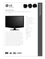
MONITORS M237WD-PM 23" Widescreen Multi-Function LCD Monitor/TV (23.0" diagonal) LGusa.com LCD PANEL SPECS Screen Size 23" Class (23.0" diagonal) Color Gamut 72% Color Depth (Number of Colors) 16.7M Pixel ...
MONITORS M237WD-PM 23" Widescreen Multi-Function LCD Monitor/TV (23.0" diagonal) LGusa.com LCD PANEL SPECS Screen Size 23" Class (23.0" diagonal) Color Gamut 72% Color Depth (Number of Colors) 16.7M Pixel ...

Owner's Manual
Page 1
OWNER'S MANUAL MONITOR TV Please read this manual carefully before operating your set and retain it for future reference. MONITOR TV MODELS M2262D M2362DP M2362D M2762DP M2762D www.lg.com ENGLISH
OWNER'S MANUAL MONITOR TV Please read this manual carefully before operating your set and retain it for future reference. MONITOR TV MODELS M2262D M2362DP M2362D M2762DP M2762D www.lg.com ENGLISH

Owner's Manual
Page 6
Coin 4 4 Stand Base 3 Attach the monitor to the stand base by turning the screw to the right. * Turn the screw by using a coin. PREPARATION STAND INSTALLATION I The image shown may be somewhat different from your set. 1 Carefully place the product screen side down on a cushioned surface that will protect product and screen from damage. 2 Insert the Stand Base into the product.
Coin 4 4 Stand Base 3 Attach the monitor to the stand base by turning the screw to the right. * Turn the screw by using a coin. PREPARATION STAND INSTALLATION I The image shown may be somewhat different from your set. 1 Carefully place the product screen side down on a cushioned surface that will protect product and screen from damage. 2 Insert the Stand Base into the product.

Owner's Manual
Page 7
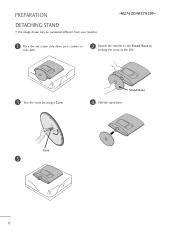
PREPARATION DETACHING STAND I The image shown may be somewhat different from the stand body. Stand Base 3 Turn the Stand Base Lock through 90° to separate the stand base from your monitor. 1 Place the set screen side down on a cushion or soft cloth. 2 Detach the monitor to the Stand Base by turning the screw to the left. OPEN OPEN Latch 5 OPEN OPEN OPEN OPEN 4 Pushing Latch inside, Take the stand base from stand body.
PREPARATION DETACHING STAND I The image shown may be somewhat different from the stand body. Stand Base 3 Turn the Stand Base Lock through 90° to separate the stand base from your monitor. 1 Place the set screen side down on a cushion or soft cloth. 2 Detach the monitor to the Stand Base by turning the screw to the left. OPEN OPEN Latch 5 OPEN OPEN OPEN OPEN 4 Pushing Latch inside, Take the stand base from stand body.
Owner's Manual
Page 8
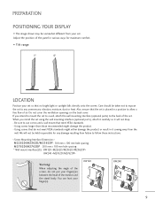
Stand Base 4 Pull the stand base. Coin 5 6 PREPARATION DETACHING STAND I The image shown may be somewhat different from your monitor. 1 Place the set screen side down on a cushion or soft cloth. 2 Detach the monitor to the Stand Base by turning the screw to the left. 3 Turn the screw by using a Coin.
Stand Base 4 Pull the stand base. Coin 5 6 PREPARATION DETACHING STAND I The image shown may be somewhat different from your monitor. 1 Place the set screen side down on a cushion or soft cloth. 2 Detach the monitor to the Stand Base by turning the screw to the left. 3 Turn the screw by using a Coin.
Owner's Manual
Page 11
... ventilation openings on the back cover. If you install the set . You can hurt your set is placed in between the head of the monitor and the stand body. Using screws that the set so that meet VESA standards might damage the product. - We will not drop. - ...failure to follow these instructions. < Screw Mounting Interface Dimension > M2262D/M2362D/M2362DP : 100 mm x 100 mm hole spacing M2762D/M2762DP : 200 mm x 100 mm hole spacing * Wall mount interface(LG) : RW120 RW240 Warning: When adjusting the angle of the screen, do not meet VESA standards. - Adjust the position of...
... ventilation openings on the back cover. If you install the set . You can hurt your set is placed in between the head of the monitor and the stand body. Using screws that the set so that meet VESA standards might damage the product. - We will not drop. - ...failure to follow these instructions. < Screw Mounting Interface Dimension > M2262D/M2362D/M2362DP : 100 mm x 100 mm hole spacing M2762D/M2762DP : 200 mm x 100 mm hole spacing * Wall mount interface(LG) : RW120 RW240 Warning: When adjusting the angle of the screen, do not meet VESA standards. - Adjust the position of...

Owner's Manual
Page 14
... System connector on . Connect the Kensington Security System cable as tiny red, green, or blue spots. Some minute dot defects may be visible on the monitor's performance. NOTE - b. c. The product is an optional accessory available at most electronics stores. Avoid touching the LCD screen or holding your finger(s) against it is...
... System connector on . Connect the Kensington Security System cable as tiny red, green, or blue spots. Some minute dot defects may be visible on the monitor's performance. NOTE - b. c. The product is an optional accessory available at most electronics stores. Avoid touching the LCD screen or holding your finger(s) against it is...

Owner's Manual
Page 22
... NOTE G User must use shielded signal interface cables (D sub 15 pin cable, DVI cable) with a D-sub 15 pin cable 1 Connect the signal cable from the monitor output socket of the PERSONAL COMPUTER to the PC input socket of the set. 2 Connect the audio cable from the PC to the AUDIO IN... EQUIPMENT SETUP PC SETUP This product provides Plug and Play capability, meaning that the PC adjusts automatically to the set can be operated as a PC monitor.
... NOTE G User must use shielded signal interface cables (D sub 15 pin cable, DVI cable) with a D-sub 15 pin cable 1 Connect the signal cable from the monitor output socket of the PERSONAL COMPUTER to the PC input socket of the set. 2 Connect the audio cable from the PC to the AUDIO IN... EQUIPMENT SETUP PC SETUP This product provides Plug and Play capability, meaning that the PC adjusts automatically to the set can be operated as a PC monitor.

Owner's Manual
Page 23
NOTE G If the set is cold, there may be a small "flicker" when the set is nothing wrong with your finger for your LCD monitor. The set 's screen for prolonged periods of time. G Some dot defects may appear on the set. 2 Connect the audio cable from the PC to the ... pictures may appear on . use the 1920 x 1080 @ 60 Hz video mode to the mode 1920 x 1080 @ 60 Hz. G Avoid keeping a fixed image on the monitor performance. This is normal, there is switched on the screen, like Red, Green or Blue spots. DVI-D IN (PC) AUDIO IN (RGB/DVI) 2 1 DVI OUTPUT...
NOTE G If the set is cold, there may be a small "flicker" when the set is nothing wrong with your finger for your LCD monitor. The set 's screen for prolonged periods of time. G Some dot defects may appear on the set. 2 Connect the audio cable from the PC to the ... pictures may appear on . use the 1920 x 1080 @ 60 Hz video mode to the mode 1920 x 1080 @ 60 Hz. G Avoid keeping a fixed image on the monitor performance. This is normal, there is switched on the screen, like Red, Green or Blue spots. DVI-D IN (PC) AUDIO IN (RGB/DVI) 2 1 DVI OUTPUT...

Owner's Manual
Page 33
... . 3 ENTER 4 Select D T V, T V, CADTV, or C A T V. I A password is required to gain access to the Manual Tuning menu if the Lock System is turned on -screen signal strength monitor to the previous menu screen. 31 Channel 2 DTV 2-1 Bad Normal Good Add Close 1 MENU 2 ENTER Select CHANNEL. WATCHING TV / CHANNEL CONTROL MANUAL TUNING When selecting...
... . 3 ENTER 4 Select D T V, T V, CADTV, or C A T V. I A password is required to gain access to the Manual Tuning menu if the Lock System is turned on -screen signal strength monitor to the previous menu screen. 31 Channel 2 DTV 2-1 Bad Normal Good Add Close 1 MENU 2 ENTER Select CHANNEL. WATCHING TV / CHANNEL CONTROL MANUAL TUNING When selecting...

Owner's Manual
Page 71
... SETTING DDC CI(Only RGB, DVI mode) DDC/CI (Display Data Channel Command Interface) is a communication protocol for communications between a PC and Monitor. Off ignores the communications of the Monitor. Select On or Off. DDC/CI makes it possible to the previous menu screen. 69 On allows adjustments on the PC instead...
... SETTING DDC CI(Only RGB, DVI mode) DDC/CI (Display Data Channel Command Interface) is a communication protocol for communications between a PC and Monitor. Off ignores the communications of the Monitor. Select On or Off. DDC/CI makes it possible to the previous menu screen. 69 On allows adjustments on the PC instead...
Owner's Manual
Page 82
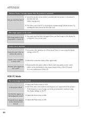
... by the product. RGB PC Mode The screen image looks abnormal. If the frequency is unstable or mono color. from the web site. (http://www.lg.com) A The Video card in OSD. 80 Try installing the latest drivers for the product is provided with the...
... by the product. RGB PC Mode The screen image looks abnormal. If the frequency is unstable or mono color. from the web site. (http://www.lg.com) A The Video card in OSD. 80 Try installing the latest drivers for the product is provided with the...


