
User Manual
Page 1
ThinkPad Edge 14″, Edge 15″, E40, and E50 Hardware Maintenance Manual
ThinkPad Edge 14″, Edge 15″, E40, and E50 Hardware Maintenance Manual

User Manual
Page 3
ThinkPad Edge 14″, Edge 15″, E40, and E50 Hardware Maintenance Manual
ThinkPad Edge 14″, Edge 15″, E40, and E50 Hardware Maintenance Manual

User Manual
Page 6
Miscellaneous parts 173 AC adapters 174 Power cords 175 Recovery discs 176 Windows 7 Home Basic (32 bit) DVDs . . . . 176 Windows 7 Home Premium (32 bit) DVDs . . 177 Windows 7 Home Premium (64 bit) DVDs . . 178 Windows 7 Professional (32 bit) DVDs . . . . 179 Windows 7 Professional (64 bit) DVDs . . . . 181 Common service tools 183 Notices 185 Trademarks 186 iv ThinkPad Edge 14″, Edge 15″, E40, and E50 Hardware Maintenance Manual
Miscellaneous parts 173 AC adapters 174 Power cords 175 Recovery discs 176 Windows 7 Home Basic (32 bit) DVDs . . . . 176 Windows 7 Home Premium (32 bit) DVDs . . 177 Windows 7 Home Premium (64 bit) DVDs . . 178 Windows 7 Professional (32 bit) DVDs . . . . 179 Windows 7 Professional (64 bit) DVDs . . . . 181 Common service tools 183 Notices 185 Trademarks 186 iv ThinkPad Edge 14″, Edge 15″, E40, and E50 Hardware Maintenance Manual

User Manual
Page 7
...and 0579 ThinkPad Edge 15″ and E50 MT 0301, 0302, and 0319 Use this manual along with the advanced diagnostic tests to troubleshoot problems effectively. Before servicing a ThinkPad Notebook product, be sure to troubleshoot problems. Important: This manual is intended only for the following ThinkPad® ... products. About this manual This manual contains service and reference information for trained service technicians who are familiar with ThinkPad Notebook products. Use this manual along with the advanced diagnostic tests to read all the information under "Safety information...
...and 0579 ThinkPad Edge 15″ and E50 MT 0301, 0302, and 0319 Use this manual along with the advanced diagnostic tests to troubleshoot problems effectively. Before servicing a ThinkPad Notebook product, be sure to troubleshoot problems. Important: This manual is intended only for the following ThinkPad® ... products. About this manual This manual contains service and reference information for trained service technicians who are familiar with ThinkPad Notebook products. Use this manual along with the advanced diagnostic tests to read all the information under "Safety information...

User Manual
Page 8
vi ThinkPad Edge 14″, Edge 15″, E40, and E50 Hardware Maintenance Manual
vi ThinkPad Edge 14″, Edge 15″, E40, and E50 Hardware Maintenance Manual

User Manual
Page 10
... loose clothing that is long, fasten it . v Insert the ends of your necktie or scarf inside clothing or fasten it with labels or stickers. 2 ThinkPad Edge 14″, Edge 15″, E40, and E50 Hardware Maintenance Manual v Wear safety glasses when you can be hazardous to your eyes. Replace any other service technicians and...
... loose clothing that is long, fasten it . v Insert the ends of your necktie or scarf inside clothing or fasten it with labels or stickers. 2 ThinkPad Edge 14″, Edge 15″, E40, and E50 Hardware Maintenance Manual v Wear safety glasses when you can be hazardous to your eyes. Replace any other service technicians and...

User Manual
Page 12
... - Switch off power. - such touching can cause personal injury and machine damage. Pumps - do not become a victim yourself. - Similar units to get medical aid. 4 ThinkPad Edge 14″, Edge 15″, E40, and E50 Hardware Maintenance Manual Use caution; v If an electrical accident occurs: - v Do not touch live electrical circuits with the power on...
... - Switch off power. - such touching can cause personal injury and machine damage. Pumps - do not become a victim yourself. - Similar units to get medical aid. 4 ThinkPad Edge 14″, Edge 15″, E40, and E50 Hardware Maintenance Manual Use caution; v If an electrical accident occurs: - v Do not touch live electrical circuits with the power on...

User Manual
Page 14
... a grounding system, such as fully effective. Make sure that meets the specific service requirement. v Wear a grounded wrist strap against ESD damage by a certified electrician. 6 ThinkPad Edge 14″, Edge 15″, E40, and E50 Hardware Maintenance Manual v Use a grounded work mat to provide a static-free work mat, and the person handling the part are...
... a grounding system, such as fully effective. Make sure that meets the specific service requirement. v Wear a grounded wrist strap against ESD damage by a certified electrician. 6 ThinkPad Edge 14″, Edge 15″, E40, and E50 Hardware Maintenance Manual v Use a grounded work mat to provide a static-free work mat, and the person handling the part are...

User Manual
Page 16
...into your eyes or on after FRU replacement, make sure all screws, springs, and other small parts are present after washing. 8 ThinkPad Edge 14″, Edge 15″, E40, and E50 Hardware Maintenance Manual DANGER The lithium battery can result in ignition or explosion of an incorrect battery can cause...metal flakes can result in ignition or explosion of the battery pack as required by shaking the computer and listening for at least 15 minutes. Dispose of an incorrect battery can cause electrical shorts. Dispose of the battery. DANGER Before the computer is powered on ...
...into your eyes or on after FRU replacement, make sure all screws, springs, and other small parts are present after washing. 8 ThinkPad Edge 14″, Edge 15″, E40, and E50 Hardware Maintenance Manual DANGER The lithium battery can result in ignition or explosion of an incorrect battery can cause...metal flakes can result in ignition or explosion of the battery pack as required by shaking the computer and listening for at least 15 minutes. Dispose of an incorrect battery can cause electrical shorts. Dispose of the battery. DANGER Before the computer is powered on ...

User Manual
Page 18
10 ThinkPad Edge 14″, Edge 15″, E40, and E50 Hardware Maintenance Manual
10 ThinkPad Edge 14″, Edge 15″, E40, and E50 Hardware Maintenance Manual
User Manual
Page 94
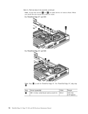
When you attach the fan, secure the screws in order, but do not remove them. For ThinkPad Edge 14″, skip step 3. For ThinkPad Edge 15″ and E50: 2c 3 2b 2a 2e 2d 2f For ThinkPad Edge 14″ and E40: 2c 2b 2a 2d Note: Step 3 is only for ThinkPad Edge 15″. Step 3 Screw (quantity) M2 × 4 mm, wafer-head, nylon-coated (1) Color Silver Torque 0.181 Nm (1.85 kgfcm) 86 ThinkPad Edge 14″, Edge 15″, E40, and E50 Hardware Maintenance Manual Removal steps of fan assembly (continued) Note: Loosen the screws 2a to 2f in order. Table 14.
When you attach the fan, secure the screws in order, but do not remove them. For ThinkPad Edge 14″, skip step 3. For ThinkPad Edge 15″ and E50: 2c 3 2b 2a 2e 2d 2f For ThinkPad Edge 14″ and E40: 2c 2b 2a 2d Note: Step 3 is only for ThinkPad Edge 15″. Step 3 Screw (quantity) M2 × 4 mm, wafer-head, nylon-coated (1) Color Silver Torque 0.181 Nm (1.85 kgfcm) 86 ThinkPad Edge 14″, Edge 15″, E40, and E50 Hardware Maintenance Manual Removal steps of fan assembly (continued) Note: Loosen the screws 2a to 2f in order. Table 14.

User Manual
Page 116
Removal steps of LCD unit (continued) Steps 5a are for ThinkPad Edge 14″ and E40, and steps 5b are for ThinkPad Edge 15″ and E50. 5a 5b 5a 5b 5a 5a 5b 5b Step Screw (quantity) 5a or M2.5 × 6.5 mm, wafter-head, nylon-coated 5b (4) Color Black Torque 0.392 Nm (4 kgfcm) 108 ThinkPad Edge 14″, Edge 15″, E40, and E50 Hardware Maintenance Manual Table 26.
Removal steps of LCD unit (continued) Steps 5a are for ThinkPad Edge 14″ and E40, and steps 5b are for ThinkPad Edge 15″ and E50. 5a 5b 5a 5b 5a 5a 5b 5b Step Screw (quantity) 5a or M2.5 × 6.5 mm, wafter-head, nylon-coated 5b (4) Color Black Torque 0.392 Nm (4 kgfcm) 108 ThinkPad Edge 14″, Edge 15″, E40, and E50 Hardware Maintenance Manual Table 26.

User Manual
Page 118
... Keyboard" on page 100 v "1150 Keyboard bezel" on page 103 v "1160 LCD unit" on page 106 Table 27. Removal steps of top shielding assembly For ThinkPad Edge 15″ and E50: 12 3 2 2 2 3 2 4 Step 1 Screw (quantity) M2 × 2 mm, wafer-head, nylon-coated (3) Color Silver 2 M2 × 3 mm, wafer-head, nylon-coated (5) Black 3 M2... × 5 mm, wafer-head, nylon-coated (2) Black Torque 0.181 Nm (1.85 kgfcm) 0.181 Nm (1.85 kgfcm) 0.181 Nm (1.85 kgfcm) 110 ThinkPad Edge 14″, Edge 15″, E40, and E50 Hardware Maintenance Manual
... Keyboard" on page 100 v "1150 Keyboard bezel" on page 103 v "1160 LCD unit" on page 106 Table 27. Removal steps of top shielding assembly For ThinkPad Edge 15″ and E50: 12 3 2 2 2 3 2 4 Step 1 Screw (quantity) M2 × 2 mm, wafer-head, nylon-coated (3) Color Silver 2 M2 × 3 mm, wafer-head, nylon-coated (5) Black 3 M2... × 5 mm, wafer-head, nylon-coated (2) Black Torque 0.181 Nm (1.85 kgfcm) 0.181 Nm (1.85 kgfcm) 0.181 Nm (1.85 kgfcm) 110 ThinkPad Edge 14″, Edge 15″, E40, and E50 Hardware Maintenance Manual

User Manual
Page 122
Location of major sensitive components on the system board (continued) For ThinkPad Edge 15″ and E50 integrated models: a b c For ThinkPad Edge 15″ and E50 discrete models: a b d c 114 ThinkPad Edge 14″, Edge 15″, E40, and E50 Hardware Maintenance Manual Table 28.
Location of major sensitive components on the system board (continued) For ThinkPad Edge 15″ and E50 integrated models: a b c For ThinkPad Edge 15″ and E50 discrete models: a b d c 114 ThinkPad Edge 14″, Edge 15″, E40, and E50 Hardware Maintenance Manual Table 28.

User Manual
Page 123
Removal steps of system board assembly For ThinkPad Edge 15″ and E50: 1 1 1 1 Step 1 Screw (quantity) M2 × 5 mm, wafer-head, nylon-coated (4) Color Black Torque 0.181 Nm (1.85 kgfcm) For ThinkPad Edge 14″ and E40: 1 1 Step 1 Screw (quantity) M2 × 5 mm, wafer-head, nylon-coated (2) Color Black Torque 0.181 Nm (1.85 kgfcm) Removing and replacing a FRU 115 Table 29.
Removal steps of system board assembly For ThinkPad Edge 15″ and E50: 1 1 1 1 Step 1 Screw (quantity) M2 × 5 mm, wafer-head, nylon-coated (4) Color Black Torque 0.181 Nm (1.85 kgfcm) For ThinkPad Edge 14″ and E40: 1 1 Step 1 Screw (quantity) M2 × 5 mm, wafer-head, nylon-coated (2) Color Black Torque 0.181 Nm (1.85 kgfcm) Removing and replacing a FRU 115 Table 29.

User Manual
Page 126
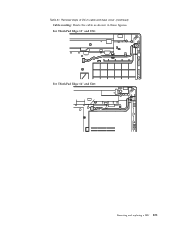
For ThinkPad Edge 15″ and E50: For ThinkPad Edge 14″ and E40: 118 ThinkPad Edge 14″, Edge 15″, E40, and E50 Hardware Maintenance Manual Removal steps of USB connector board and USB cable assembly (continued) Cable routing: Route the USB cable assembly as shown in these figures. Table 30.
For ThinkPad Edge 15″ and E50: For ThinkPad Edge 14″ and E40: 118 ThinkPad Edge 14″, Edge 15″, E40, and E50 Hardware Maintenance Manual Removal steps of USB connector board and USB cable assembly (continued) Cable routing: Route the USB cable assembly as shown in these figures. Table 30.

User Manual
Page 127
1200 DC-in cable and base cover For access, remove these FRUs in cable and base cover For ThinkPad Edge 15″ and E50: 4 3 1 2 Step 1 Screw (quantity) M2 × 3 mm, wafer-head, nylon-coated (2) Color Black Torque 0.181 Nm (1.85 kgfcm) Removing and replacing a FRU 119 ...
1200 DC-in cable and base cover For access, remove these FRUs in cable and base cover For ThinkPad Edge 15″ and E50: 4 3 1 2 Step 1 Screw (quantity) M2 × 3 mm, wafer-head, nylon-coated (2) Color Black Torque 0.181 Nm (1.85 kgfcm) Removing and replacing a FRU 119 ...
User Manual
Page 129
For ThinkPad Edge 15″ and E50: For ThinkPad Edge 14″ and E40: Removing and replacing a FRU 121 Table 31. Removal steps of DC-in cable and base cover (continued) Cable routing: Route the cable as shown in these figures.
For ThinkPad Edge 15″ and E50: For ThinkPad Edge 14″ and E40: Removing and replacing a FRU 121 Table 31. Removal steps of DC-in cable and base cover (continued) Cable routing: Route the cable as shown in these figures.

User Manual
Page 130
... Anatel BG label 11 Israel label (SIM model) 12 Brazil Anatel Bluetooth label For some models, you also need to apply the following figures: For ThinkPad Edge 15″ and E50: 1 2 3 4 12 5 11 6 7 10 9 8 122 ThinkPad Edge 14″, Edge 15″, E40, and E50 Hardware Maintenance Manual
... Anatel BG label 11 Israel label (SIM model) 12 Brazil Anatel Bluetooth label For some models, you also need to apply the following figures: For ThinkPad Edge 15″ and E50: 1 2 3 4 12 5 11 6 7 10 9 8 122 ThinkPad Edge 14″, Edge 15″, E40, and E50 Hardware Maintenance Manual

User Manual
Page 135
... page 106 v "2010 LCD front bezel" on page 124 Table 35. Removal steps of hinges, LCD panel, LCD cable, and LCD rear cover assembly For ThinkPad Edge 15″ and E50: 1 1 11 2 2 2 2 Step 1 Screw (quantity) M2 × 5 mm, wafer-head, nylon-coated (4) Color Black Torque 0.181 Nm (1.85 kgfcm) Removing and replacing a FRU...
... page 106 v "2010 LCD front bezel" on page 124 Table 35. Removal steps of hinges, LCD panel, LCD cable, and LCD rear cover assembly For ThinkPad Edge 15″ and E50: 1 1 11 2 2 2 2 Step 1 Screw (quantity) M2 × 5 mm, wafer-head, nylon-coated (4) Color Black Torque 0.181 Nm (1.85 kgfcm) Removing and replacing a FRU...


