User Manual
Page 5
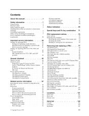
... and GAV products 42 General checkout 45 What to do first 46 Checkout guide 47 Diagnostics using PC-Doctor for DOS . . . . 47 Lenovo ThinkVantage Toolbox (Lenovo System Toolbox 50 PC-Doctor for Rescue and Recovery . . . . . 50 FRU tests 51 Power system checkout 53 Checking the ac adapter 53... PCI Express Mini Card for wireless LAN . . . 96 1120 Backup battery 98 1130 Bluetooth daughter card (BDC-2) . . . . . 99 1140 Keyboard 100 1150 Keyboard bezel 103 1160 LCD unit 106 1170 Top shielding assembly 110 1180 System board assembly 112 1190 USB connector board and USB cable assembly...
... and GAV products 42 General checkout 45 What to do first 46 Checkout guide 47 Diagnostics using PC-Doctor for DOS . . . . 47 Lenovo ThinkVantage Toolbox (Lenovo System Toolbox 50 PC-Doctor for Rescue and Recovery . . . . . 50 FRU tests 51 Power system checkout 53 Checking the ac adapter 53... PCI Express Mini Card for wireless LAN . . . 96 1120 Backup battery 98 1130 Bluetooth daughter card (BDC-2) . . . . . 99 1140 Keyboard 100 1150 Keyboard bezel 103 1160 LCD unit 106 1170 Top shielding assembly 110 1180 System board assembly 112 1190 USB connector board and USB cable assembly...

User Manual
Page 54
... __ 7. Following is covered under the warranty by referring to the following list: The following symptoms might indicate damage caused by spilling a liquid onto the keyboard v Use of an incorrect ac adapter on laptop products The following are not covered under warranty and some common items that are not covered under...
... __ 7. Following is covered under the warranty by referring to the following list: The following symptoms might indicate damage caused by spilling a liquid onto the keyboard v Use of an incorrect ac adapter on laptop products The following are not covered under warranty and some common items that are not covered under...

User Manual
Page 57
... board v Video Adapter v Serial Ports v Fixed Disks v Diskette Drives v Other Devices v Wireless LAN v Advanced Memory Tests v Keyboard v Video v Internal Speaker v Mouse v Diskette v System Load v Optical Drive Test v Intel WLAN Radio Test Note: v In the Keyboard test in Interactive Tests, the Fn key should be set to the computer, detach it cannot be...
... board v Video Adapter v Serial Ports v Fixed Disks v Diskette Drives v Other Devices v Wireless LAN v Advanced Memory Tests v Keyboard v Video v Internal Speaker v Mouse v Diskette v System Load v Optical Drive Test v Intel WLAN Radio Test Note: v In the Keyboard test in Interactive Tests, the Fn key should be set to the computer, detach it cannot be...
User Manual
Page 59
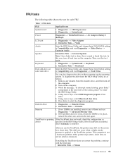
FRU tests The following : v Interactive Tests --> Mouse General checkout 51 Table 1. Diagnostics --> Systemboard --> Keyboard 2. Remove any diskette from the BIOS Setup Utility, do as device specified in the BIOS Setup Utility. Using cursor keys... without starting up the operating system. FRU tests FRU Applicable test System board 1. Diagnostics --> Video Adapter 2. In this test again. Keyboard 1. Interactive Tests --> Keyboard Hard disk drive or solid state drive Enter the BIOS Setup Utility and change Serial ATA (SATA) setting to Compatibility, and run Diagnostics...
FRU tests The following : v Interactive Tests --> Mouse General checkout 51 Table 1. Diagnostics --> Systemboard --> Keyboard 2. Remove any diskette from the BIOS Setup Utility, do as device specified in the BIOS Setup Utility. Using cursor keys... without starting up the operating system. FRU tests FRU Applicable test System board 1. Diagnostics --> Video Adapter 2. In this test again. Keyboard 1. Interactive Tests --> Keyboard Hard disk drive or solid state drive Enter the BIOS Setup Utility and change Serial ATA (SATA) setting to Compatibility, and run Diagnostics...
User Manual
Page 71
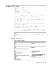
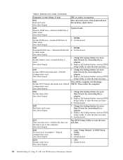
...: For a device not supported by pressing F10. 2. Battery pack. 0191 System Security-Invalid Remote Change requested. 1. System board. 0210 Stuck Key (two short beeps) Change keyboard, and restart the computer. A numeric error is not correct. (two short beeps) 0190 Critical low-battery error (two short beeps) 1. Invalid RFID configuration information area...
...: For a device not supported by pressing F10. 2. Battery pack. 0191 System Security-Invalid Remote Change requested. 1. System board. 0210 Stuck Key (two short beeps) Change keyboard, and restart the computer. A numeric error is not correct. (two short beeps) 0190 Critical low-battery error (two short beeps) 1. Invalid RFID configuration information area...
User Manual
Page 72
... backup battery and run BIOS Setup Utility to reset the time and date. 3. Table 2. Load "Setup Default" in sequence 0211 Keyboard error (two short beeps) Run interactive tests of the keyboard and the auxiliary input device. 0230 Shadow RAM error-Shadow RAM fails at offset nnnn. (two short beeps) System board. 0231...
... backup battery and run BIOS Setup Utility to reset the time and date. 3. Table 2. Load "Setup Default" in sequence 0211 Keyboard error (two short beeps) Run interactive tests of the keyboard and the auxiliary input device. 0230 Shadow RAM error-Shadow RAM fails at offset nnnn. (two short beeps) System board. 0231...

User Manual
Page 79
...display and an external monitor, the Win+P key combination is to change the brightness level temporarily. To use the Power Manager. © Copyright Lenovo 2010 71 The following table shows the function of the Power Option in the Control Panel or use F1 - Speaker volume down (F2) Speaker...setting. Note: To use the Power Manager. The computer display becomes dimmer. To change the default brightness level, change the settings of the keyboard. Special keys and Fn key combination This computer has several special keys at the upper row of the Power Option in the Control Panel ...
...display and an external monitor, the Win+P key combination is to change the brightness level temporarily. To use the Power Manager. © Copyright Lenovo 2010 71 The following table shows the function of the Power Option in the Control Panel or use F1 - Speaker volume down (F2) Speaker...setting. Note: To use the Power Manager. The computer display becomes dimmer. To change the default brightness level, change the settings of the keyboard. Special keys and Fn key combination This computer has several special keys at the upper row of the Power Option in the Control Panel ...

User Manual
Page 80
... 14″, Edge 15″, E40, and E50 Hardware Maintenance Manual If you press this function, following device drivers must be installed on the keyboard illumination and then turn the computer off, put it in the list. Note: To use this key, a list of each feature in sleep ...or hibernation mode, the keyboard illumination setting is displayed. Table 7. Special keys and Fn key combination (continued) Special key or Fn Description key combination Wireless radio control (F9) Enable...
... 14″, Edge 15″, E40, and E50 Hardware Maintenance Manual If you press this function, following device drivers must be installed on the keyboard illumination and then turn the computer off, put it in the list. Note: To use this key, a list of each feature in sleep ...or hibernation mode, the keyboard illumination setting is displayed. Table 7. Special keys and Fn key combination (continued) Special key or Fn Description key combination Wireless radio control (F9) Enable...

User Manual
Page 103
Removing and replacing a FRU 95 Installation of the palm rest firmly fit into place. 4. Attach the cables to secure the palm rest. Push the front side of the palm rest until it clicks into the guide holes of the keyboard bezel as shown in this figure. 3. Attach the palm rest so that the two small projections of palm rest assembly with cables When installing: 1. Table 19. Then fasten the screws to the system board firmly. 2. Close the LCD cover and turn the computer over.
Removing and replacing a FRU 95 Installation of the palm rest firmly fit into place. 4. Attach the cables to secure the palm rest. Push the front side of the palm rest until it clicks into the guide holes of the keyboard bezel as shown in this figure. 3. Attach the palm rest so that the two small projections of palm rest assembly with cables When installing: 1. Table 19. Then fasten the screws to the system board firmly. 2. Close the LCD cover and turn the computer over.

User Manual
Page 108
1140 Keyboard For access, remove these FRUs in order: v "1010 Battery pack" on page 78 v "1030 Optical drive or travel cover" on page 80 v "1100 Palm rest assembly with cables" on page 93 Table 23. Removal steps of keyboard 1 1 Step 1 Screw (quantity) M2 × 5 mm, wafer-head, nylon-coated (1) Color Black Torque 0.181 Nm (1.85 kgfcm) 100 ThinkPad Edge 14″, Edge 15″, E40, and E50 Hardware Maintenance Manual
1140 Keyboard For access, remove these FRUs in order: v "1010 Battery pack" on page 78 v "1030 Optical drive or travel cover" on page 80 v "1100 Palm rest assembly with cables" on page 93 Table 23. Removal steps of keyboard 1 1 Step 1 Screw (quantity) M2 × 5 mm, wafer-head, nylon-coated (1) Color Black Torque 0.181 Nm (1.85 kgfcm) 100 ThinkPad Edge 14″, Edge 15″, E40, and E50 Hardware Maintenance Manual

User Manual
Page 109
Table 23. Removal steps of keyboard (continued) 2 3 2 4 5 Step 6 Screw (quantity) M2 × 3 mm, wafer-head, nylon-coated (1) Color Black 7 M2 × 2 mm, wafer-head, nylon-coated (1) Silver Torque 0.181 Nm (1.85 kgfcm) 0.181 Nm (1.85 kgfcm) 6 Removing and replacing a FRU 101
Table 23. Removal steps of keyboard (continued) 2 3 2 4 5 Step 6 Screw (quantity) M2 × 3 mm, wafer-head, nylon-coated (1) Color Black 7 M2 × 2 mm, wafer-head, nylon-coated (1) Silver Torque 0.181 Nm (1.85 kgfcm) 0.181 Nm (1.85 kgfcm) 6 Removing and replacing a FRU 101

User Manual
Page 110
Attach the keyboard so that the front side of the keyboard is housed firmly, gently press the keys with your thumbs and try to slide the keyboard toward you. 4. Attach the connectors. 2. Secure the keyboard by tightening the screws from the bottom side of the keyboard 1. To make sure that the keyboard edges are under the frame as follows: Table 24. When installing the keyboard, do as shown in this figure. 3. Installation of the computer. 102 ThinkPad Edge 14″, Edge 15″, E40, and E50 Hardware Maintenance Manual
Attach the keyboard so that the front side of the keyboard is housed firmly, gently press the keys with your thumbs and try to slide the keyboard toward you. 4. Attach the connectors. 2. Secure the keyboard by tightening the screws from the bottom side of the keyboard 1. To make sure that the keyboard edges are under the frame as follows: Table 24. When installing the keyboard, do as shown in this figure. 3. Installation of the computer. 102 ThinkPad Edge 14″, Edge 15″, E40, and E50 Hardware Maintenance Manual

User Manual
Page 111
1150 Keyboard bezel For access, remove these FRUs in order: v "1010 Battery pack" on page 78 v "1030 Optical drive or travel cover" on page 80 v "1100 Palm rest assembly with cables" on page 93 v "1140 Keyboard" on page 100 Table 25. Removal steps of keyboard bezel 1 2 2 2 2 2 1 Step 1 2 Screw (quantity) M2.5 × 6.5 mm, wafer-head, nylon-coated (2) M2 × 3 mm, wafer-head, nylon-coated (5) Color Black Black Torque 0.392 Nm (4 kgfcm) 0.181 Nm (1.85 kgfcm) Removing and replacing a FRU 103
1150 Keyboard bezel For access, remove these FRUs in order: v "1010 Battery pack" on page 78 v "1030 Optical drive or travel cover" on page 80 v "1100 Palm rest assembly with cables" on page 93 v "1140 Keyboard" on page 100 Table 25. Removal steps of keyboard bezel 1 2 2 2 2 2 1 Step 1 2 Screw (quantity) M2.5 × 6.5 mm, wafer-head, nylon-coated (2) M2 × 3 mm, wafer-head, nylon-coated (5) Color Black Black Torque 0.392 Nm (4 kgfcm) 0.181 Nm (1.85 kgfcm) Removing and replacing a FRU 103

User Manual
Page 112
Removal steps of keyboard bezel (continued) 3 6 3 4 5 Step 3 Screw (quantity) M2 × 3 mm, wafer-head, nylon-coated (2) Color Black Torque 0.181 Nm (1.85 kgfcm) When installing: Make sure that the connectors are attached firmly to the system board. 104 ThinkPad Edge 14″, Edge 15″, E40, and E50 Hardware Maintenance Manual Table 25.
Removal steps of keyboard bezel (continued) 3 6 3 4 5 Step 3 Screw (quantity) M2 × 3 mm, wafer-head, nylon-coated (2) Color Black Torque 0.181 Nm (1.85 kgfcm) When installing: Make sure that the connectors are attached firmly to the system board. 104 ThinkPad Edge 14″, Edge 15″, E40, and E50 Hardware Maintenance Manual Table 25.

User Manual
Page 113
Table 25. Removal steps of keyboard bezel (continued) 8 8 7 Removing and replacing a FRU 105
Table 25. Removal steps of keyboard bezel (continued) 8 8 7 Removing and replacing a FRU 105

User Manual
Page 114
... page 90 v "1100 Palm rest assembly with cables" on page 93 v "1110 PCI Express Mini Card for wireless LAN" on page 96 v "1140 Keyboard" on page 100 v "1150 Keyboard bezel" on page 103 Table 26. Removal steps of LCD unit 1 1 Step 1 Screw (quantity) M2.5 × 6.5 mm, wafter-head, nylon-coated (2) Color Black...
... page 90 v "1100 Palm rest assembly with cables" on page 93 v "1110 PCI Express Mini Card for wireless LAN" on page 96 v "1140 Keyboard" on page 100 v "1150 Keyboard bezel" on page 103 Table 26. Removal steps of LCD unit 1 1 Step 1 Screw (quantity) M2.5 × 6.5 mm, wafter-head, nylon-coated (2) Color Black...

User Manual
Page 118
... WAN" on page 90 v "1100 Palm rest assembly with cables" on page 93 v "1110 PCI Express Mini Card for wireless LAN" on page 96 v "1140 Keyboard" on page 100 v "1150 Keyboard bezel" on page 103 v "1160 LCD unit" on page 106 Table 27.
... WAN" on page 90 v "1100 Palm rest assembly with cables" on page 93 v "1110 PCI Express Mini Card for wireless LAN" on page 96 v "1140 Keyboard" on page 100 v "1150 Keyboard bezel" on page 103 v "1160 LCD unit" on page 106 Table 27.

User Manual
Page 120
... Mini Card for wireless LAN" on page 96 v "1120 Backup battery" on page 98 v "1130 Bluetooth daughter card (BDC-2)" on page 99 v "1140 Keyboard" on page 100 v "1150 Keyboard bezel" on page 103 v "1160 LCD unit" on page 106 v "1170 Top shielding assembly" on page 110 112 ThinkPad Edge 14″, Edge...
... Mini Card for wireless LAN" on page 96 v "1120 Backup battery" on page 98 v "1130 Bluetooth daughter card (BDC-2)" on page 99 v "1140 Keyboard" on page 100 v "1150 Keyboard bezel" on page 103 v "1160 LCD unit" on page 106 v "1170 Top shielding assembly" on page 110 112 ThinkPad Edge 14″, Edge...

User Manual
Page 125
... WAN" on page 90 v "1100 Palm rest assembly with cables" on page 93 v "1110 PCI Express Mini Card for wireless LAN" on page 96 v "1140 Keyboard" on page 100 v "1150 Keyboard bezel" on page 103 v "1160 LCD unit" on page 106 v "1170 Top shielding assembly" on page 110 Table 30.
... WAN" on page 90 v "1100 Palm rest assembly with cables" on page 93 v "1110 PCI Express Mini Card for wireless LAN" on page 96 v "1140 Keyboard" on page 100 v "1150 Keyboard bezel" on page 103 v "1160 LCD unit" on page 106 v "1170 Top shielding assembly" on page 110 Table 30.

User Manual
Page 127
... Mini Card for wireless LAN" on page 96 v "1120 Backup battery" on page 98 v "1130 Bluetooth daughter card (BDC-2)" on page 99 v "1140 Keyboard" on page 100 v "1150 Keyboard bezel" on page 103 v "1160 LCD unit" on page 106 v "1170 Top shielding assembly" on page 110 v "1180 System board assembly" on page...
... Mini Card for wireless LAN" on page 96 v "1120 Backup battery" on page 98 v "1130 Bluetooth daughter card (BDC-2)" on page 99 v "1140 Keyboard" on page 100 v "1150 Keyboard bezel" on page 103 v "1160 LCD unit" on page 106 v "1170 Top shielding assembly" on page 110 v "1180 System board assembly" on page...


