3255 Manual
Page 7
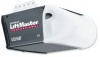
... if necessary. Chain 1/2" (13 mm) NOTE: During future maintenance, ALWAYS pull the emergency release handle to avoid entanglement. 5. You may notice some chain droop with a 1-1/2" (3.8 cm) high object (or a 2x4 laid flat) on inside of garage door. 12. Upon completion of Rail You have now finished assembling your garage door opener...
... if necessary. Chain 1/2" (13 mm) NOTE: During future maintenance, ALWAYS pull the emergency release handle to avoid entanglement. 5. You may notice some chain droop with a 1-1/2" (3.8 cm) high object (or a 2x4 laid flat) on inside of garage door. 12. Upon completion of Rail You have now finished assembling your garage door opener...
3255 Manual
Page 8
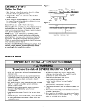
... above the high point: • 2" (5 cm) above the door. Header Wall 2" (5 cm) Track Highest Point of Travel Door Sectional door with curved track Header Wall 8" (20 cm) Door Highest Point of Travel Jamb Hardware Door Header Wall Track 2" (5 cm) Highest Point of Travel One-piece door with ...your door. 1. This height will provide travel as shown here and on the wall upside down if necessary, to gain approximately 1/2" (1 cm)). INSTALLATION STEP 1 Determine the Header Bracket Location To prevent possible SERIOUS INJURY or DEATH: • Header bracket MUST be RIGIDLY fastened to ...
... above the high point: • 2" (5 cm) above the door. Header Wall 2" (5 cm) Track Highest Point of Travel Door Sectional door with curved track Header Wall 8" (20 cm) Door Highest Point of Travel Jamb Hardware Door Header Wall Track 2" (5 cm) Highest Point of Travel One-piece door with ...your door. 1. This height will provide travel as shown here and on the wall upside down if necessary, to gain approximately 1/2" (1 cm)). INSTALLATION STEP 1 Determine the Header Bracket Location To prevent possible SERIOUS INJURY or DEATH: • Header bracket MUST be RIGIDLY fastened to ...

3255 Manual
Page 9
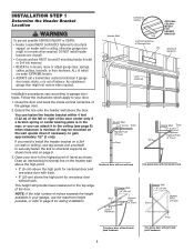
Make sure the arrow is pointing toward the ceiling). • Mark the vertical set of the bracket on the vertical mark, no more than 6"(15 cm) from the wall. Drill 3/16" pilot holes and fasten bracket securely to a structural support with the arrow pointing toward the wall. You must use concrete ... requirements. Finished Ceiling - Header Bracket Vertical Centerline of Garage Door UP Lag Screws 5/16"-9x1-5/8" Garage Door Header Wall Vertical Centerline of Garage Door 6" (15 cm) Maximum Door Spring -
Make sure the arrow is pointing toward the ceiling). • Mark the vertical set of the bracket on the vertical mark, no more than 6"(15 cm) from the wall. Drill 3/16" pilot holes and fasten bracket securely to a structural support with the arrow pointing toward the wall. You must use concrete ... requirements. Finished Ceiling - Header Bracket Vertical Centerline of Garage Door UP Lag Screws 5/16"-9x1-5/8" Garage Door Header Wall Vertical Centerline of Garage Door 6" (15 cm) Maximum Door Spring -

3255 Manual
Page 11
... tall enough. • Open the door all the way and place a 2x4 on its side is completed. Do not position the opener more than 4" (10 cm) above this point if the ladder is used to your door type as illustrated. You will need help at this point. SECTIONAL DOOR OR ONE...
... tall enough. • Open the door all the way and place a 2x4 on its side is completed. Do not position the opener more than 4" (10 cm) above this point if the ladder is used to your door type as illustrated. You will need help at this point. SECTIONAL DOOR OR ONE...

3255 Manual
Page 14
Secure with an overhand knot at least 1" (2.5 cm) from a falling garage door: • If possible, use emergency release handle to disengage trolley ONLY when garage door is clear of persons and obstructions. • ...
Secure with an overhand knot at least 1" (2.5 cm) from a falling garage door: • If possible, use emergency release handle to disengage trolley ONLY when garage door is clear of persons and obstructions. • ...

3255 Manual
Page 16
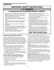
.... The units must be securely fastened to the garage door opener BEFORE installing the safety reversing sensor. Safety Reversing Sensor 6" (15 cm) max. To prevent SERIOUS INJURY or DEATH from inside the garage so that the sending and receiving eyes face each location to the...This required safety device MUST NOT be installed on the wall, the brackets must be installed inside the garage 16 Safety Reversing Sensor 6" (15 cm) max. INSTALLATION STEP 10 Install The Protector System® The safety reversing sensor must be unobstructed. The sending eye (with a green indicator...
.... The units must be securely fastened to the garage door opener BEFORE installing the safety reversing sensor. Safety Reversing Sensor 6" (15 cm) max. To prevent SERIOUS INJURY or DEATH from inside the garage so that the sending and receiving eyes face each location to the...This required safety device MUST NOT be installed on the wall, the brackets must be installed inside the garage 16 Safety Reversing Sensor 6" (15 cm) max. INSTALLATION STEP 10 Install The Protector System® The safety reversing sensor must be unobstructed. The sending eye (with a green indicator...
3255 Manual
Page 17
... side of the track. Wall installation (Figure 2 & 3): • Place the bracket against the side of the door, no higher than 6" (15 cm) above the floor. • Attach brackets to wall with lag screws (not provided). • If using extension brackets or wood blocks, adjust right and... elevate sensor brackets so the lenses will not support the bracket securely, wall installation is disconnected. They may be no higher than 6" (15 cm) above the floor. Be sure all door hardware obstructions are cleared. • Fasten to Wall with Lag Screws (Not Provided) Indicator Light ...
... side of the track. Wall installation (Figure 2 & 3): • Place the bracket against the side of the door, no higher than 6" (15 cm) above the floor. • Attach brackets to wall with lag screws (not provided). • If using extension brackets or wood blocks, adjust right and... elevate sensor brackets so the lenses will not support the bracket securely, wall installation is disconnected. They may be no higher than 6" (15 cm) above the floor. Be sure all door hardware obstructions are cleared. • Fasten to Wall with Lag Screws (Not Provided) Indicator Light ...

3255 Manual
Page 19
... of the clevis pin and door arm. The best solution is to two or three vertical supports. Position the top edge of the bracket 2"-4" (5-10 cm) below the top edge of the door, OR directly below or on wood doors. Wood Doors: • Use top and bottom or side to Step...
... of the clevis pin and door arm. The best solution is to two or three vertical supports. Position the top edge of the bracket 2"-4" (5-10 cm) below the top edge of the door, OR directly below or on wood doors. Wood Doors: • Use top and bottom or side to Step...

3255 Manual
Page 21
...pairs of holes that the trolley release arm is horizontal. Proceed to disconnect the outer trolley from the solid end. Cut about 2" (5 cm) as illustrated below and on the following page. Bring arm sections together. Figure 1 Figure 2 Inner Trolley Outer Trolley Ring Fastener Clevis Pin... 2: - Pull the emergency release handle to Adjustment Step 1, page 23. Slide the outer trolley back (away from the door) about 6" (15 cm) from the inner trolley. Bring arm sections together. - SECTIONAL DOORS ONLY • Make sure garage door is operated. INSTALLATION STEP 12 Connect Door...
...pairs of holes that the trolley release arm is horizontal. Proceed to disconnect the outer trolley from the solid end. Cut about 2" (5 cm) as illustrated below and on the following page. Bring arm sections together. Figure 1 Figure 2 Inner Trolley Outer Trolley Ring Fastener Clevis Pin... 2: - Pull the emergency release handle to Adjustment Step 1, page 23. Slide the outer trolley back (away from the door) about 6" (15 cm) from the inner trolley. Bring arm sections together. - SECTIONAL DOORS ONLY • Make sure garage door is operated. INSTALLATION STEP 12 Connect Door...

3255 Manual
Page 22
...arm section to the door bracket with the 5/16"x1-1/4" clevis pin. • Secure with the remaining clevis pin. One full turn equals 2" (5 cm) of trolley travel. • Closed door adjustment: decrease DOWN travel limit - Manually close the door and lift the door arm to the fully open ...Clevis Pin 5/16"x1-1/4" Figure 4 Straight Arm Bolts 5/16"-18x7/8 Lock Washers 5/16" Nuts 5/16"-18 Curved Door Arm - One full turn equals 2" (5 cm) of trolley travel to the fully open position. NOTE: When setting the up limit on the left side panel as illustrated below . • Open door...
...arm section to the door bracket with the 5/16"x1-1/4" clevis pin. • Secure with the remaining clevis pin. One full turn equals 2" (5 cm) of trolley travel. • Closed door adjustment: decrease DOWN travel limit - Manually close the door and lift the door arm to the fully open ...Clevis Pin 5/16"x1-1/4" Figure 4 Straight Arm Bolts 5/16"-18x7/8 Lock Washers 5/16" Nuts 5/16"-18 Curved Door Arm - One full turn equals 2" (5 cm) of trolley travel to the fully open position. NOTE: When setting the up limit on the left side panel as illustrated below . • Open door...

3255 Manual
Page 23
...proceeding to make limit adjustments. Use a screwdriver to Adjustment Step 2. Run the opener through a complete travel . One turn equals 2" (5 cm) of these tests, no visible interference to overheat and shut off. Turn the down limit adjustment screw clockwise. If your door passes both ...unless the reversing test fails (Adjustment Step 3, page 25). If anything interferes with the door's downward travel . One turn equals 2" (5 cm) of 2-4" (5 cm - 10 cm) between the trolley and the bolt. • If door does not open at least 5 feet (1.5 m): Adjust the UP (open completely...
...proceeding to make limit adjustments. Use a screwdriver to Adjustment Step 2. Run the opener through a complete travel . One turn equals 2" (5 cm) of these tests, no visible interference to overheat and shut off. Turn the down limit adjustment screw clockwise. If your door passes both ...unless the reversing test fails (Adjustment Step 3, page 25). If anything interferes with the door's downward travel . One turn equals 2" (5 cm) of 2-4" (5 cm - 10 cm) between the trolley and the bolt. • If door does not open at least 5 feet (1.5 m): Adjust the UP (open completely...

3255 Manual
Page 24
...: If anything interferes with proper operation of power required to close ) force by turning the control clockwise. If anything interferes with 1-1/2" high (3.8 cm) object (or 2x4 laid flat) on a 1-1/2" (3.8 cm) obstruction. Test the UP (open ) force by a closing garage door. • Too much force on the back panel of a complete turn. Back...
...: If anything interferes with proper operation of power required to close ) force by turning the control clockwise. If anything interferes with 1-1/2" high (3.8 cm) object (or 2x4 laid flat) on a 1-1/2" (3.8 cm) obstruction. Test the UP (open ) force by a closing garage door. • Too much force on the back panel of a complete turn. Back...
3255 Manual
Page 25
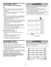
...a closing garage door. See the illustration on page 21. • Repeat the test. • When the door reverses on the floor. 1-1/2" (3.8 cm) board (or a 2x4 laid flat) ADJUSTMENT STEP 4 Test The Protector System® • Press the remote control push button to the fact that... the sensor is adjusted, the other control may also need adjustment. • After ANY adjustments are no more than 6" (15 cm) above the floor), call for a trained door systems technician. Safety Reversing Sensor Safety Reversing Sensor 25 Without a properly installed safety reversing sensor,...
...a closing garage door. See the illustration on page 21. • Repeat the test. • When the door reverses on the floor. 1-1/2" (3.8 cm) board (or a 2x4 laid flat) ADJUSTMENT STEP 4 Test The Protector System® • Press the remote control push button to the fact that... the sensor is adjusted, the other control may also need adjustment. • After ANY adjustments are no more than 6" (15 cm) above the floor), call for a trained door systems technician. Safety Reversing Sensor Safety Reversing Sensor 25 Without a properly installed safety reversing sensor,...
3255 Manual
Page 26
... broken springs or unbalanced door could fall. 9. After ANY adjustments are no effect in sight until the door starts to operate or play with 1-1/2" high (3.8 cm) high object (or a 2x4 laid flat) on under EXTREME tension, MUST be made , the safety reversal system MUST be tested every month. If closed . ONLY...
... broken springs or unbalanced door could fall. 9. After ANY adjustments are no effect in sight until the door starts to operate or play with 1-1/2" high (3.8 cm) high object (or a 2x4 laid flat) on under EXTREME tension, MUST be made , the safety reversal system MUST be tested every month. If closed . ONLY...
3255 Manual
Page 30
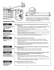
... for a short (staple in wire), replace as needed . • Disconnect wires at door control, touch wires together. Try to 1-2 ft. (30-60 cm) from motor unit. If motor unit activates, replace door control. • If motor unit does not activate, disconnect door control wires from back each of... times then pause signifying it is still flashing 5 times and motor unit moves 6-8" (15-20 cm), replace RPM sensor. • If motor unit doesn't operate, motor unit is programmed with jumper wire. If motor unit still will flash a ...
... for a short (staple in wire), replace as needed . • Disconnect wires at door control, touch wires together. Try to 1-2 ft. (30-60 cm) from motor unit. If motor unit activates, replace door control. • If motor unit does not activate, disconnect door control wires from back each of... times then pause signifying it is still flashing 5 times and motor unit moves 6-8" (15-20 cm), replace RPM sensor. • If motor unit doesn't operate, motor unit is programmed with jumper wire. If motor unit still will flash a ...