GT- Logic 4 Installation Manual
Page 2
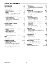
...Specifications 4-5 Maximum Door Area 5 Weights and Dimensions 6 ASSEMBLY 7-9 Assemble the Operator (Models T and GT 7 Install the Chain (Models T and GT 8 Assemble the Operator (Model APT 9 TYPICAL INSTALLATION 10-12 Install the Header Bracket 10 Attach the Track to ...LiftMaster Monitored Entrapment Protection (LMEP) Devices 22 ADJUSTMENT 23-24 Limit Adjustment 23 Clutch Adjustment (Belt Drive Model Operators 24 TESTING 25 MANUAL RELEASE 26-27 Emergency Disconnect System Model GT and T 26 Emergency Disconnect System Model APT 26 Emergency Disconnect System Model...
...Specifications 4-5 Maximum Door Area 5 Weights and Dimensions 6 ASSEMBLY 7-9 Assemble the Operator (Models T and GT 7 Install the Chain (Models T and GT 8 Assemble the Operator (Model APT 9 TYPICAL INSTALLATION 10-12 Install the Header Bracket 10 Attach the Track to ...LiftMaster Monitored Entrapment Protection (LMEP) Devices 22 ADJUSTMENT 23-24 Limit Adjustment 23 Clutch Adjustment (Belt Drive Model Operators 24 TESTING 25 MANUAL RELEASE 26-27 Emergency Disconnect System Model GT and T 26 Emergency Disconnect System Model APT 26 Emergency Disconnect System Model...
GT- Logic 4 Installation Manual
Page 4
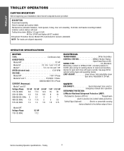
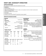
... attached to provide non-contact safety protection. Carton inventory/Operator specifications - Trolley 4 ENTRAPMENT PROTECTION: LiftMaster Monitored Entrapment Protection (LMEP) Photoelectric Sensors (CPS-U Through beam used to the bottom edge of door. DESCRIPTION...5.6 6.8 8 10 208/230-3Ø, 60Hz 3 3.1 4 6 7 460-3Ø, 60Hz 1.5 1.75 2 3 3.5 575-3Ø, 60Hz 1.3 1.4 1.6 1.8 2.75 Model APT Voltage-Phase 115-1Ø, 60Hz 1/2 HP 11.2 ELECTRICAL TRANSFORMER 24Vac Secondary CONTROL STATION NEMA 3-Button Station Open/Close/Stop w/LED WIRING TYPE C2 (Standard...
... attached to provide non-contact safety protection. Carton inventory/Operator specifications - Trolley 4 ENTRAPMENT PROTECTION: LiftMaster Monitored Entrapment Protection (LMEP) Photoelectric Sensors (CPS-U Through beam used to the bottom edge of door. DESCRIPTION...5.6 6.8 8 10 208/230-3Ø, 60Hz 3 3.1 4 6 7 460-3Ø, 60Hz 1.5 1.75 2 3 3.5 575-3Ø, 60Hz 1.3 1.4 1.6 1.8 2.75 Model APT Voltage-Phase 115-1Ø, 60Hz 1/2 HP 11.2 ELECTRICAL TRANSFORMER 24Vac Secondary CONTROL STATION NEMA 3-Button Station Open/Close/Stop w/LED WIRING TYPE C2 (Standard...
GT- Logic 4 Installation Manual
Page 5
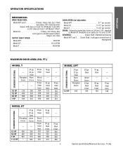
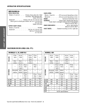
...Doors 24 ga. Steel Insul. 200 250 300 380 5 Operator specifications/Maximum door area - Output: #48 chain (1/3 and 1/2 HP Model T and APT) or #41 chain (3/4 and 1 HP Model T ONLY) Model GT Primary: 20:1 Heavy duty worm gear-in-oil-bath speed reducer Output: #41 chain OUTPUT SHAFT SPEED...: Model APT 96 RPM Model GT 113.5 RPM Model T 140 RPM DOOR SPEED (not adjustable): Model APT 6-7" per second Model GT 11-12" per second Model T 11-12" per second BRAKE: Solenoid actuated disc brake on 3/4 and 1 HP, ...
...Doors 24 ga. Steel Insul. 200 250 300 380 5 Operator specifications/Maximum door area - Output: #48 chain (1/3 and 1/2 HP Model T and APT) or #41 chain (3/4 and 1 HP Model T ONLY) Model GT Primary: 20:1 Heavy duty worm gear-in-oil-bath speed reducer Output: #41 chain OUTPUT SHAFT SPEED...: Model APT 96 RPM Model GT 113.5 RPM Model T 140 RPM DOOR SPEED (not adjustable): Model APT 6-7" per second Model GT 11-12" per second Model T 11-12" per second BRAKE: Solenoid actuated disc brake on 3/4 and 1 HP, ...
GT- Logic 4 Installation Manual
Page 6
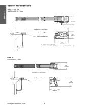
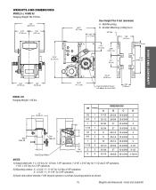
Trolley 6 Optional on APT, T 3/4 and T 1 HP models; TROLLEY WEIGHTS AND DIMENSIONS MODELS T AND APT Hanging Weight: 80-110 lbs. 4" (10.16 cm) 14" (35.56 cm) *Door Height Plus 4 feet (minimum) Highest Point of Door Travel 11.63" (29.54 cm) *23.43" (59.51 cm) *- For Units with Brake add 3-1/2" (Standard on T 1/3 and 1/2 HP models) MODEL GT Hanging Weight: 140 lbs. 4" (10.16 cm) Door Height Plus 4 feet (minimum) 13.05" (33.15 cm) * 17.5" (44.45 cm) 18.5" (46.99 cm) Weights and dimensions -
Trolley 6 Optional on APT, T 3/4 and T 1 HP models; TROLLEY WEIGHTS AND DIMENSIONS MODELS T AND APT Hanging Weight: 80-110 lbs. 4" (10.16 cm) 14" (35.56 cm) *Door Height Plus 4 feet (minimum) Highest Point of Door Travel 11.63" (29.54 cm) *23.43" (59.51 cm) *- For Units with Brake add 3-1/2" (Standard on T 1/3 and 1/2 HP models) MODEL GT Hanging Weight: 140 lbs. 4" (10.16 cm) Door Height Plus 4 feet (minimum) 13.05" (33.15 cm) * 17.5" (44.45 cm) 18.5" (46.99 cm) Weights and dimensions -
GT- Logic 4 Installation Manual
Page 7
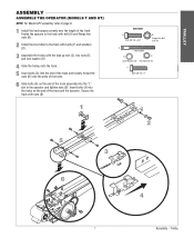
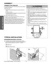
... length of the track and the operator. Insert bolts (A) into the "L" slot in the operator and tighten nuts (B). TROLLEY ASSEMBLY ASSEMBLE THE OPERATOR (MODELS T AND GT) NOTE: For Model APT assembly refer to the track with bolts (F) and washers (D). 3 Assemble the trolley with the take up bolt (C), hex nuts (E), and lock washer...
... length of the track and the operator. Insert bolts (A) into the "L" slot in the operator and tighten nuts (B). TROLLEY ASSEMBLY ASSEMBLE THE OPERATOR (MODELS T AND GT) NOTE: For Model APT assembly refer to the track with bolts (F) and washers (D). 3 Assemble the trolley with the take up bolt (C), hex nuts (E), and lock washer...
GT- Logic 4 Installation Manual
Page 8
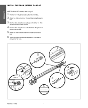
TROLLEY INSTALL THE CHAIN (MODELS T AND GT) NOTE: For Model APT assembly refer to page 9. 1 Position the trolley 2 inches away from the front idler. 2 Attach the chain to the trolley threaded shaft using the master ... chain to the operator. Wrap the chain around the operator drive sprocket. 4 Run the chain along the track to the front of the track. 2 1 2˝ MODEL T 3 MODEL GT 4 5 6 3˝ Assembly -
TROLLEY INSTALL THE CHAIN (MODELS T AND GT) NOTE: For Model APT assembly refer to page 9. 1 Position the trolley 2 inches away from the front idler. 2 Attach the chain to the trolley threaded shaft using the master ... chain to the operator. Wrap the chain around the operator drive sprocket. 4 Run the chain along the track to the front of the track. 2 1 2˝ MODEL T 3 MODEL GT 4 5 6 3˝ Assembly -
GT- Logic 4 Installation Manual
Page 9
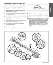
... along the track to adjust the slack of the track. Wrap the chain around the operator drive sprocket. 2 6 1 3 8 9 10 3˝ 9 4 7 5 Assembly - TROLLEY ASSEMBLE THE OPERATOR (MODEL APT) NOTE: If your model is no binding. 7 Run the chain along the track to the next page.
... along the track to adjust the slack of the track. Wrap the chain around the operator drive sprocket. 2 6 1 3 8 9 10 3˝ 9 4 7 5 Assembly - TROLLEY ASSEMBLE THE OPERATOR (MODEL APT) NOTE: If your model is no binding. 7 Run the chain along the track to the next page.
GT- Logic 4 Installation Manual
Page 13
See page 29 for manual door operation Model HJ Includes both floor level disconnect systems stated above ENTRAPMENT PROTECTION: LiftMaster Monitored Entrapment Protection (LMEP) Photoelectric Sensors (CPS-U Through beam used to open ...115-1Ø, 60Hz 8.5 11.2 13.6 16 230-1Ø, 60Hz 4.2 5.6 6.8 8 208/230-3Ø, 60Hz 3 3.1 4 6 460-3Ø, 60Hz 1.5 1.75 2 3 575-3Ø, 60Hz 1.3 1.4 1.6 1.8 Model GH Voltage-Phase 1/2 HP 3/4 HP 1 HP 1-1/2 HP 2 HP 3 HP 115-1Ø, 60Hz 11.2 13.6 16 20 - - 230-1Ø, 60Hz 5.6 6.8 8 10 - - 208/230-3Ø, 60Hz 3.1...
See page 29 for manual door operation Model HJ Includes both floor level disconnect systems stated above ENTRAPMENT PROTECTION: LiftMaster Monitored Entrapment Protection (LMEP) Photoelectric Sensors (CPS-U Through beam used to open ...115-1Ø, 60Hz 8.5 11.2 13.6 16 230-1Ø, 60Hz 4.2 5.6 6.8 8 208/230-3Ø, 60Hz 3 3.1 4 6 460-3Ø, 60Hz 1.5 1.75 2 3 575-3Ø, 60Hz 1.3 1.4 1.6 1.8 Model GH Voltage-Phase 1/2 HP 3/4 HP 1 HP 1-1/2 HP 2 HP 3 HP 115-1Ø, 60Hz 11.2 13.6 16 20 - - 230-1Ø, 60Hz 5.6 6.8 8 10 - - 208/230-3Ø, 60Hz 3.1...
GT- Logic 4 Installation Manual
Page 14
... Worm gear-in-oil bath gear reducer 44:1 for 1-1/2 and 2 HP 42:1 for 3 HP Output: #50 chain OUTPUT SHAFT SPEED: Model J, H and HJ 36 RPM Model GH 38.3 for 1/2, 3/4 and 1 HP 39.2 for 1-1/2 and 2 HP 41.1 for specifications 16 ga. Steel Steel Grilles --- ...Alum. Steel --- 20 ga. Grilles --- Steel Alum. Doors 24 ga. 22 ga. Steel --- 16 ga. Hoist and Jackshaft 14 OPERATOR SPECIFICATIONS MECHANICAL DRIVE REDUCTION: Model J, H, and HJ Primary: Heavy duty (5L) V-Belt Secondary: #48 chain/sprocket; SECTIONAL Fiberglass Doors --- 1/2 HP 325 3/4 HP 480 1 HP 650 ...
... Worm gear-in-oil bath gear reducer 44:1 for 1-1/2 and 2 HP 42:1 for 3 HP Output: #50 chain OUTPUT SHAFT SPEED: Model J, H and HJ 36 RPM Model GH 38.3 for 1/2, 3/4 and 1 HP 39.2 for 1-1/2 and 2 HP 41.1 for specifications 16 ga. Steel Steel Grilles --- ...Alum. Steel --- 20 ga. Grilles --- Steel Alum. Doors 24 ga. 22 ga. Steel --- 16 ga. Hoist and Jackshaft 14 OPERATOR SPECIFICATIONS MECHANICAL DRIVE REDUCTION: Model J, H, and HJ Primary: Heavy duty (5L) V-Belt Secondary: #48 chain/sprocket; SECTIONAL Fiberglass Doors --- 1/2 HP 325 3/4 HP 480 1 HP 650 ...
GT- Logic 4 Installation Manual
Page 15
.../64 3-1/2 27 13-63/64 3-1/2 28-5/8 15-15/64 3-15/16 NOTES: 1) Output shaft with Models H and HJ ONLY 4.56" (11.58 cm) HOIST AND JACKSHAFT MODEL GH Hanging Weight: 140 lbs. Hoist and Jackshaft WEIGHTS AND DIMENSIONS MODELS J, H AND HJ Hanging Weight: 80-110 lbs. 14.5" (36.83 cm) 6.94" (17.63...
.../64 3-1/2 27 13-63/64 3-1/2 28-5/8 15-15/64 3-15/16 NOTES: 1) Output shaft with Models H and HJ ONLY 4.56" (11.58 cm) HOIST AND JACKSHAFT MODEL GH Hanging Weight: 140 lbs. Hoist and Jackshaft WEIGHTS AND DIMENSIONS MODELS J, H AND HJ Hanging Weight: 80-110 lbs. 14.5" (36.83 cm) 6.94" (17.63...
GT- Logic 4 Installation Manual
Page 16
... brackets. An unbalanced door may be mounted on the wall, shelf or bracket (not provided, see accessories). b. Right (R) or Left (L). On models J, H, HJ and GH operators the drive sprocket can cause SERIOUS PERSONAL INJURY. • Disable ALL locks and remove ALL ropes connected to door ...either the right or left side. The handing is out of the AVERTISSEMENT building. • Concrete anchors MUST be switched. AVERTISSEMENT For models H and HJ with the drive shaft parallel to prevent play between PRECAUCIÓN the door shaft and operator drive shaft is imperative that...
... brackets. An unbalanced door may be mounted on the wall, shelf or bracket (not provided, see accessories). b. Right (R) or Left (L). On models J, H, HJ and GH operators the drive sprocket can cause SERIOUS PERSONAL INJURY. • Disable ALL locks and remove ALL ropes connected to door ...either the right or left side. The handing is out of the AVERTISSEMENT building. • Concrete anchors MUST be switched. AVERTISSEMENT For models H and HJ with the drive shaft parallel to prevent play between PRECAUCIÓN the door shaft and operator drive shaft is imperative that...
GT- Logic 4 Installation Manual
Page 20
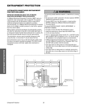
...trrRmicevaSexre.sniansbgoorve floor ADVERTENCIA ADVERTENCIA - ENTWRAAPRMNEINNGT PROTECTION WARNING LPIRFOTTCMEAACSTUTIEOTRNIOM(LONMNEIPT)ORED ENTRAPMENT IMPORTANT INFORMATION ABOUT THE LIFTMASTER MONITORED ENTRAPMENT PROTECTION DEVICES A LiftMaster Monitored Entrapment Protection (LMEP) device is required for most wiring types (refer to the door ... in the fully opened or closed position BEFORE installing the LiftMaster Monitored Entrapment Protection device. Use with the photoelectric sensors model CPS-U, additional entrapment devices are for purchase (see accessories). Right Side of ...
...trrRmicevaSexre.sniansbgoorve floor ADVERTENCIA ADVERTENCIA - ENTWRAAPRMNEINNGT PROTECTION WARNING LPIRFOTTCMEAACSTUTIEOTRNIOM(LONMNEIPT)ORED ENTRAPMENT IMPORTANT INFORMATION ABOUT THE LIFTMASTER MONITORED ENTRAPMENT PROTECTION DEVICES A LiftMaster Monitored Entrapment Protection (LMEP) device is required for most wiring types (refer to the door ... in the fully opened or closed position BEFORE installing the LiftMaster Monitored Entrapment Protection device. Use with the photoelectric sensors model CPS-U, additional entrapment devices are for purchase (see accessories). Right Side of ...
GT- Logic 4 Installation Manual
Page 22
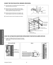
... with the provided hardware. Finger tighten the receiving sensor wing nut. above floor WIRE THE LIFTMASTER MONITORED ENTRAPMENT PROTECTION (LMEP) DEVICES 1 Connect the LiftMaster Monitored Entrapment Protection (LMEP) device to the logic board according to the models shown below ). Securely tighten the sending sensor wing nut. 3 Run the wires from both sensors...
... with the provided hardware. Finger tighten the receiving sensor wing nut. above floor WIRE THE LIFTMASTER MONITORED ENTRAPMENT PROTECTION (LMEP) DEVICES 1 Connect the LiftMaster Monitored Entrapment Protection (LMEP) device to the logic board according to the models shown below ). Securely tighten the sending sensor wing nut. 3 Run the wires from both sensors...

GT- Logic 4 Installation Manual
Page 24
... need for a safety sensing device. We require the use of motor failures is eliminated. (Auxiliary Reversal System not applicable on models GH and GT.) NOTE: This feature is automatically learned and does not require programming. Clutch adjustment 24 LOSE OPEN RPM Sensor Logic... the cotter pin from electrocution: • Disconnect electric power BEFORE performing ANY adjustments or maintenance. 12 4 AV3ERTISSEMENT ATTENTION ADJUST TORQUE LIMITER CLUTCH (MODEL GT) 1 Loosen set screws of torque adjustment nut on the gear reducer. 2 Back off clutch nut until there is very little tension on...
... need for a safety sensing device. We require the use of motor failures is eliminated. (Auxiliary Reversal System not applicable on models GH and GT.) NOTE: This feature is automatically learned and does not require programming. Clutch adjustment 24 LOSE OPEN RPM Sensor Logic... the cotter pin from electrocution: • Disconnect electric power BEFORE performing ANY adjustments or maintenance. 12 4 AV3ERTISSEMENT ATTENTION ADJUST TORQUE LIMITER CLUTCH (MODEL GT) 1 Loosen set screws of torque adjustment nut on the gear reducer. 2 Back off clutch nut until there is very little tension on...
GT- Logic 4 Installation Manual
Page 26
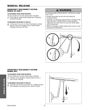
... will close. TO RECONNECT DOOR ARM TO TROLLEY 2 Lift free end of persons and obstructions. 1 AVERTISSEMENT ATTENTION 2 NOTICE MANUAL RELEASE EMERGENCY DISCONNECT SYSTEM MODEL APT TO DISCONNECT DOOR FROM OPERATOR The door should be in the fully closed position if possible. 1 Pull emergency release handle straight down on the... next UP or DOWN operation, either manually or by using the door control or remote. MANUAL RELEASE EMERGENCY DISCONNECT SYSTEM MODEL GT AND T TO DISCONNECT DOOR FROM OPERATOR The door should be in the fully closed position if possible. 1 Pull down .
... will close. TO RECONNECT DOOR ARM TO TROLLEY 2 Lift free end of persons and obstructions. 1 AVERTISSEMENT ATTENTION 2 NOTICE MANUAL RELEASE EMERGENCY DISCONNECT SYSTEM MODEL APT TO DISCONNECT DOOR FROM OPERATOR The door should be in the fully closed position if possible. 1 Pull emergency release handle straight down on the... next UP or DOWN operation, either manually or by using the door control or remote. MANUAL RELEASE EMERGENCY DISCONNECT SYSTEM MODEL GT AND T TO DISCONNECT DOOR FROM OPERATOR The door should be in the fully closed position if possible. 1 Pull down .
GT- Logic 4 Installation Manual
Page 27
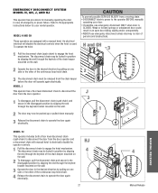
...the continuous loop hoist chain. 3 The disconnect chain must be released from the door operator and a disconnect chain with a manual hoist. MODEL J This operator has a floor level disconnect chain to disconnect the door from a moving chain: • DISCONNECT electric power to...Pull the disconnect chain (sash chain) to operate the door again electrically. HJ 4 27 3 4 2 1 Manual Release WARNING EMERGENCY DISCONNECT SYSTEM MODEL H, GH, J, AND HJ This operator has provisions for your door. • If possible, use emergency disconnect unless doorway is clear of persons ...
...the continuous loop hoist chain. 3 The disconnect chain must be released from the door operator and a disconnect chain with a manual hoist. MODEL J This operator has a floor level disconnect chain to disconnect the door from a moving chain: • DISCONNECT electric power to...Pull the disconnect chain (sash chain) to operate the door again electrically. HJ 4 27 3 4 2 1 Manual Release WARNING EMERGENCY DISCONNECT SYSTEM MODEL H, GH, J, AND HJ This operator has provisions for your door. • If possible, use emergency disconnect unless doorway is clear of persons ...
GT- Logic 4 Installation Manual
Page 36
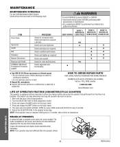
... required. HOW TO ORDER REPAIR PARTS OUR LARGE SERVICE ORGANIZATION SPANS AMERICA Installation and service information are rated for some models. Start with an odometer to show how many months and cycles the operator has performed from the time it as... grease or silicone spray). • Do not lubricate motor. ASpVrocEketRs TISSEMENLCuhTbercikcasteet. BeAlt TTENTION Check condition and tension. Bearings and Shafts LiftMaster Monitored Entrapment Protection (LMEP) Check for the life of the brake assembly. Check alignment and functionality. EVERY MONTH EVERY 3 EVERY ...
... required. HOW TO ORDER REPAIR PARTS OUR LARGE SERVICE ORGANIZATION SPANS AMERICA Installation and service information are rated for some models. Start with an odometer to show how many months and cycles the operator has performed from the time it as... grease or silicone spray). • Do not lubricate motor. ASpVrocEketRs TISSEMENLCuhTbercikcasteet. BeAlt TTENTION Check condition and tension. Bearings and Shafts LiftMaster Monitored Entrapment Protection (LMEP) Check for the life of the brake assembly. Check alignment and functionality. EVERY MONTH EVERY 3 EVERY ...
GT- Logic 4 Installation Manual
Page 41
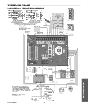
... IN (WH) COM 120 120 / 240 VAC VAC (WH) NO COM C (YE) +24 VAC -24 VAC COIL (GY) NOTE: Lock Sensor is provided on Models DJ and DH only, red wire from main harness connects to NC on Bypass L/S and to page 26 for H and HJ right hand... models and all GH and J models. WIRING DIAGRAMS LOGIC (VER. 4.0) 1 PHASE WIRING DIAGRAM 115V MOTOR CONNECTION 230V MOTOR CONNECTION NOTE: Gray (GY) and purple (PU) motor wires are reversed for LiftMaster Monitored Entrapment Protection (LMEP) device connections Hoist Interlock When Present TMR...
... IN (WH) COM 120 120 / 240 VAC VAC (WH) NO COM C (YE) +24 VAC -24 VAC COIL (GY) NOTE: Lock Sensor is provided on Models DJ and DH only, red wire from main harness connects to NC on Bypass L/S and to page 26 for H and HJ right hand... models and all GH and J models. WIRING DIAGRAMS LOGIC (VER. 4.0) 1 PHASE WIRING DIAGRAM 115V MOTOR CONNECTION 230V MOTOR CONNECTION NOTE: Gray (GY) and purple (PU) motor wires are reversed for LiftMaster Monitored Entrapment Protection (LMEP) device connections Hoist Interlock When Present TMR...
GT- Logic 4 Installation Manual
Page 42
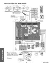
... to NC on LOCK SENSOR switch. Sensing Edge Refer to NO on BYPASS L/S and to page 26 for H and HJ right hand models and all GH and J models. POWER IN NOTE: Lock Sensor is located in the chassis. (WH) LOCK (RD) NO SENSOR (see note at left) NC ... (YE) (BL/BK) 208/230V MOTOR CONNECTION 460V MOTOR CONNECTION 575V MOTOR CONNECTION NOTE: Gray (GY) and purple (PU) motor wires are reversed for LiftMaster Monitored Entrapment Protection (LMEP) device connections Hoist Interlock When Present TMR DEF (BL) SWITCH (YE) Maintenance Alert LED (RD) (WH) Open Close Stop OPEN...
... to NC on LOCK SENSOR switch. Sensing Edge Refer to NO on BYPASS L/S and to page 26 for H and HJ right hand models and all GH and J models. POWER IN NOTE: Lock Sensor is located in the chassis. (WH) LOCK (RD) NO SENSOR (see note at left) NC ... (YE) (BL/BK) 208/230V MOTOR CONNECTION 460V MOTOR CONNECTION 575V MOTOR CONNECTION NOTE: Gray (GY) and purple (PU) motor wires are reversed for LiftMaster Monitored Entrapment Protection (LMEP) device connections Hoist Interlock When Present TMR DEF (BL) SWITCH (YE) Maintenance Alert LED (RD) (WH) Open Close Stop OPEN...
GT- Logic 4 User Manual
Page 6
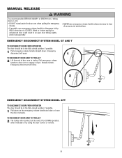
... release handle to allow arm to disengage trolley ONLY when door is clear release. AVE AV 2 NOTICE EMERGENCY DISCONNECT SYSTEM MODEL APT TO DISCONNECT DOOR FROM OPERATOR ADVERTENCIA The door should be in the fully closed position if possible. MANUAL RELEASE WARNING ...fully closed position if possible. 1 Pull down . Emergency disconnect will open door falling rapidly and/or unexpectedly. Release handle. EMERGENCY DISCONNECT SYSTEM MODEL GT AND T TO DISCONNECT DOOR FROM OPERATOR The door should be in an open . 1 TO RECONNECT DOOR ARM TO TROLLEY ATTENTION 2 Lift...
... release handle to allow arm to disengage trolley ONLY when door is clear release. AVE AV 2 NOTICE EMERGENCY DISCONNECT SYSTEM MODEL APT TO DISCONNECT DOOR FROM OPERATOR ADVERTENCIA The door should be in the fully closed position if possible. MANUAL RELEASE WARNING ...fully closed position if possible. 1 Pull down . Emergency disconnect will open door falling rapidly and/or unexpectedly. Release handle. EMERGENCY DISCONNECT SYSTEM MODEL GT AND T TO DISCONNECT DOOR FROM OPERATOR The door should be in an open . 1 TO RECONNECT DOOR ARM TO TROLLEY ATTENTION 2 Lift...


